- 您现在的位置:买卖IC网 > PDF目录19337 > LT1768IGN#TRPBF (Linear Technology)IC CTRLR CCFL SGL/MULT HP 16SSOP PDF资料下载
参数资料
| 型号: | LT1768IGN#TRPBF |
| 厂商: | Linear Technology |
| 文件页数: | 12/20页 |
| 文件大小: | 0K |
| 描述: | IC CTRLR CCFL SGL/MULT HP 16SSOP |
| 标准包装: | 2,500 |
| 类型: | CCFL 控制器 |
| 频率: | 300 ~ 410 kHz |
| 电流 - 电源: | 7mA |
| 电流 - 输出: | 1.5A |
| 电源电压: | 9 V ~ 24 V |
| 工作温度: | -40°C ~ 125°C |
| 封装/外壳: | 16-SSOP(0.154",3.90mm 宽) |
| 供应商设备封装: | 16-SSOP |
| 包装: | 带卷 (TR) |
�� �
�
�LT1768�
�APPLICATIO� N� S� I� N� FOR� M� ATIO� N�
�and� is� dependant� on� the� operating� mode.� For� dual� lamp�
�displays,� the� transfer� function� for� minimum� current� mode�
�(I� DIO� /I� RMIN� )� is� equal� to� 10A/A,� and� for� maximum� current�
�mode� (I� DIO� /I� RMAX� )� is� equal� to� 100A/A.�
�The� transfer� functions� discussed� above� are� between� R� MAX�
�and� R� MIN� current� and� average� lamp� current� not� RMS� lamp�
�current.� Due� to� the� differences� between� the� average� and�
�RMS� functions,� the� actual� overall� transfer� function� be-�
�tween� actual� lamp� current� and� R� MIN� /R� MAX� current� must� be�
�empirically� determined,� and� is� dependant� on� the� particular�
�lamp/display� housing� combination� used.� For� example,� in�
�the� circuit� of� Figure� 1� setting� R� RMIN� to� 10k� ?� and� R� RMAX� to�
�16.8� ?� ,� sets� the� minimum� and� maximum� RMS� lamp�
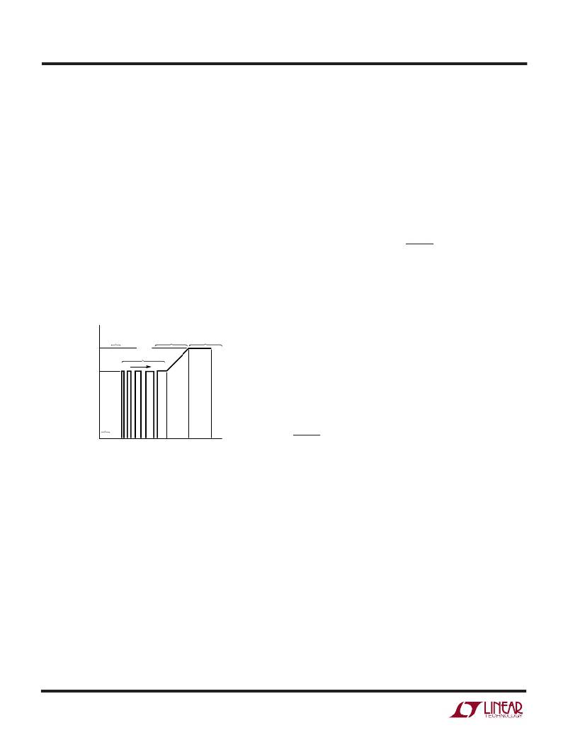
�currents� for� the� example� display� to� 1mA� and� 9mA� per� lamp�
�respectively.� Figure� 4� shows� the� lamp� current� vs� program-�
�ming� voltage� for� the� circuit� in� Figure� 1.�
�R� RMIN� adjusted� to� produce� the� specified� current.� If� a� wide�
�dimming� range� is� desired,� V� PROG� should� be� set� to� 0.75V�
�and� R� RMIN� adjusted� to� produce� the� required� dimming�
�ratio.� Care� must� be� taken� when� adjusting� R� RMIN� to� pro-�
�duce� extreme� dimming� ratios.� The� minimum� lamp� current�
�set� by� R� RMIN� must� be� able� to� fully� illuminate� the� lamp� or�
�thermometering� (uneven� illumination)� will� occur.� If� the�
�desired� dimming� ratio� can’t� be� achieved� by� adjusting�
�R� RMIN� ,� the� minimum� lamp� current� can� be� set� to� zero� by�
�connecting� the� R� MIN� pin� to� the� V� REF� pin.� If� the� minimum�
�current� is� set� to� less� than� the� open� lamp� threshold� current�
�(approximately� 125� μ� A),� the� FAULT� pin� will� be� activated� for�
�PROG� voltages� between� 0.5V� and� 1V.�
�The� values� chosen� for� R� RMAX� and� R� RMIN� are� extremely�
�critical� in� determining� the� lifetime� of� the� display.� It� is�
�imperative� that� proper� measurement� techniques,� such� as�
�those� cited� in� the� references,� be� used� when� determining�
�9mA�
�MIN�
�CURRENT�
�PWM�
�LINEAR�
�MAX�
�CURRENT�
�R� RMAX� and� R� RMIN� values.�
�I� CCFL� (mA)�
�6mA�
�(FREQ� =� 220Hz)�
�0%� 100%�
�Lamp� Fault� Modes� and� Single� Lamp� Operation�
�The� DIO� pin� diodes� that� conduct� on� the� positive� cycle� are�
�used� to� detect� open� lamp� fault� conditions.� If� the� current�
�in� either� of� the� DIO� pins� on� the� positive� half� cycle� is� less�
�than� 125� μ� A� due� to� either� an� open� lamp� or� lamp� lowside�
�OFF�
�short� to� ground,� for� a� minimum� of� 1� PWM� cycle,� then� the�
�0mA�
�0.5� 1.0�
�3V� (� V� PWM)� 4.0�
�V� PROG� (V)�
�5.0�
�1768� F04�
�FAULT� pin� will� be� activated� and� the� lamp� programming�
�current� into� the� VC� pin� in� high� level� PWM� mode,� linear�
�Figure� 4.� Lamp� Current� vs� PROG� Voltage� for�
�the� Circuit� in� Figure� 1�
�Choosing� R� RMAX� and� R� RMIN� and� V� PWM�
�The� value� for� R� RMAX� should� be� determined� by� setting�
�V� PROG� to� 4.5V� then� adjusting� R� RMAX� to� produce� the�
�maximum� allowable� current� specified� by� the� lamp� manu-�
�facturer.�
�The� voltage� for� the� PWM� pin� should� then� be� set� so� that� the�
�LT1768� normally� operates� in� linear� mode.� A� typical� value�
�for� V� PWM� is� approximately� 2.5V,� which� limits� the� PWM�
�region� to� 50%� of� the� V� PROG� input� voltage� range.�
�The� value� for� R� RMIN� should� be� chosen� to� either� produce�
�the� minimum� manufacturer� specified� lamp� current� or�
�enable� a� wide� dimming� range.� If� a� minimum� specified�
�current� is� desired,� the� V� PROG� should� be� set� to� 0.75V� and�
�12�
�mode,� and� maximum� current� mode,� will� be� reduced� by�
�approximately� 50%.� Halving� the� VC� source� current� will� cut�
�the� total� lamp� current� to� approximately� one� half� of� its�
�programmed� value.� This� function� insures� that� the� maxi-�
�mum� lamp� current� level� set� by� R� RMAX� will� not� be� exceeded�
�even� under� fault� conditions.� If� the� current� in� both� of� the�
�DIO� pins� on� the� positive� cycle� is� less� than� 125� μ� A,� and� the�
�VC� pin� hits� its� clamp� value� (indicating� an� open� lamp� or�
�lamp� lowside� short� to� ground� fault� condition)� for� a� mini-�
�mum� of� 1� PWM� cycle,� the� gate� drive� will� be� latched� off.� The�
�latch� can� be� cleared� by� setting� the� PROG� voltage� to� zero� or�
�placing� the� LT1768� in� shutdown� mode.�
�Since� open� lamp� fault� conditions� produce� high� voltage� AC�
�waveforms,� it� is� imperative� that� proper� layout� spacings�
�between� the� high� voltage� and� DIO� lines� be� observed.�
�Coupling� capacitance� as� low� as� 0.5pF� between� the� high�
�相关PDF资料 |
PDF描述 |
|---|---|
| TPSD157M016R0150 | CAP TANT 150UF 16V 20% 2917 |
| EEM28DSES | CONN EDGECARD 56POS .156 EYELET |
| BAS19LT1G | DIODE SWITCH 200MA 120V SOT23 |
| RAC05-24SA-ST | CONV AC/DC 90-264VAC 24V 200MA |
| TAP686K016CRS | CAP TANT 68UF 16V 10% RADIAL |
相关代理商/技术参数 |
参数描述 |
|---|---|
| AD5282BRU200 | 功能描述:IC DUAL POT 200K 256POS 16-TSSOP RoHS:否 类别:集成电路 (IC) >> 数据采集 - 数字电位器 系列:- 标准包装:3,000 系列:DPP 接片:32 电阻(欧姆):10k 电路数:1 温度系数:标准值 300 ppm/°C 存储器类型:非易失 接口:3 线串行(芯片选择,递增,增/减) 电源电压:2.5 V ~ 6 V 工作温度:-40°C ~ 85°C 安装类型:表面贴装 封装/外壳:8-WFDFN 裸露焊盘 供应商设备封装:8-TDFN(2x3) 包装:带卷 (TR) |
| AD5282BRU200-REEL7 | 功能描述:IC DGTL POT DUAL 256POS 16-TSSOP RoHS:否 类别:集成电路 (IC) >> 数据采集 - 数字电位器 系列:- 标准包装:3,000 系列:DPP 接片:32 电阻(欧姆):10k 电路数:1 温度系数:标准值 300 ppm/°C 存储器类型:非易失 接口:3 线串行(芯片选择,递增,增/减) 电源电压:2.5 V ~ 6 V 工作温度:-40°C ~ 85°C 安装类型:表面贴装 封装/外壳:8-WFDFN 裸露焊盘 供应商设备封装:8-TDFN(2x3) 包装:带卷 (TR) |
| AD5282BRU20-REEL7 | 制造商:Analog Devices 功能描述:DGTL POTENTIOMETER 256POS 20KOHM DUAL 16TSSOP - Tape and Reel |
| AD5282BRU20Z | 制造商:Analog Devices 功能描述:DIG POT 2CH 256 20KOHM 14TSSOP 制造商:Analog Devices 功能描述:DIG POT, 2CH, 256, 20KOHM, TSSOP-16 制造商:Analog Devices 功能描述:DIG POT, 2CH, 256, 20KOHM, 14TSSOP 制造商:Analog Devices 功能描述:DIG POT, 2CH, 256, 20KOHM, 14TSSOP, End To End Resistance:20kohm, Track Taper:Li 制造商:Analog Devices 功能描述:DIG POT, 2CH, 256, 20KOHM, 14TSSOP, End To End Resistance:20kohm, Track Taper:Linear, Resistance Tolerance: 30%, Supply Voltage Min:4.5V, Supply Voltage Max:16.5V, Potentiometer IC Case Style:TSSOP, No. of Pins:16, No. of Steps:256, , RoHS Compliant: Yes |
| AD5282BRU50 | 功能描述:IC DUAL POT 50K 256POS 16-TSSOP RoHS:否 类别:集成电路 (IC) >> 数据采集 - 数字电位器 系列:- 标准包装:3,000 系列:DPP 接片:32 电阻(欧姆):10k 电路数:1 温度系数:标准值 300 ppm/°C 存储器类型:非易失 接口:3 线串行(芯片选择,递增,增/减) 电源电压:2.5 V ~ 6 V 工作温度:-40°C ~ 85°C 安装类型:表面贴装 封装/外壳:8-WFDFN 裸露焊盘 供应商设备封装:8-TDFN(2x3) 包装:带卷 (TR) |
发布紧急采购,3分钟左右您将得到回复。