- 您现在的位置:买卖IC网 > PDF目录17729 > U2K110CG100FB-T (Taiyo Yuden)CAP ARRAY 2CH 10PF 50V 0504 PDF资料下载
参数资料
| 型号: | U2K110CG100FB-T |
| 厂商: | Taiyo Yuden |
| 文件页数: | 15/16页 |
| 文件大小: | 0K |
| 描述: | CAP ARRAY 2CH 10PF 50V 0504 |
| 标准包装: | 10 |
| 电容: | 10pF |
| 电压 - 额定: | 50V |
| 电介质材料: | 陶瓷 |
| 电容器数量: | 2 |
| 电路类型: | 隔离 |
| 温度系数: | C0G,NP0 |
| 容差: | ±10% |
| 安装类型: | 表面贴装 |
| 封装/外壳: | 0504(1210 公制) |
| 尺寸/尺寸: | 0.054" L x 0.039" W(1.37mm x 1.00mm) |
| 高度 - 座高(最大): | 0.024"(0.60mm) |
| 包装: | 剪切带 (CT) |
| 其它名称: | 587-1025-1 |
�� �
�
�■� PRECAUTIONS�
�Precautions� on� the� use� of� Multilayer� Ceramic� Capacitors�
�4. Soldering�
�◆� Selection� of� Flux�
�Since� ?ux� may� have� a� signi?cant� effect� on� the� performance� of� capacitors,� it� is� necessary� to� verify� the� following� conditions� prior� to� use;�
�(� 1� )� Flux� used� shall� be� less� than� or� equal� to� 0.1� wt%� (� in� CI� equivalent� )� of� halogenated� content.� Flux� having� a� strong� acidity� content� shall� not� be� applied.�
�(� 2� )� When� shall� capacitors� are� soldered� on� boards,� the� amount� of� ?ux� applied� shall� be� controlled� at� the� optimum� level.�
�(� 3� )� When� water-soluble� ?ux� is� used,� special� care� shall� be� taken� to� properly� clean� the� boards.�
�?� Cooling� :� The� temperature� difference� between� the� capacitors� and� cleaning� process� shall� not� be� greater� than� 100� ℃� .�
�Precautions�
�◆� Soldering�
�Temperature,� time,� amount� of� solder,� etc.� shall� be� set� in� accordance� with� their� recommended� conditions.�
�Sn-Zn� solder� paste� can� adversely� affect� MLCC� reliability.�
�Please� contact� us� prior� to� usage� of� Sn-Zn� solder.�
�◆� Selection� of� Flux�
�1-1.� When� too� much� halogenated� substance� (� Chlorine,� etc.� )� content� is� used� to� activate� ?ux,� or� highly� acidic� ?ux� is� used,� it� may� lead� to� corrosion� of� terminal� elec-�
�trodes� or� degradation� of� insulation� resistance� on� the� surfaces� of� the� capacitors.�
�1-2.� Flux� is� used� to� increase� solderability� in� wave� soldering.� However� if� too� much� ?ux� is� applied,� a� large� amount� of� ?ux� gas� may� be� emitted� and� may� adversely� affect�
�the� solderability.� To� minimize� the� amount� of� ?ux� applied,� it� is� recommended� to� use� a� ?ux-bubbling� system.�
�1-3.� Since� the� residue� of� water-soluble� ?ux� is� easily� dissolved� in� moisture� in� the� air,� the� residues� on� the� surfaces� of� capacitors� in� high� humidity� conditions� may� cause�
�a� degradation� of� insulation� resistance� and� reliability� of� the� capacitors.� Therefore,� the� cleaning� methods� and� the� capability� of� the� machines� used� shall� also� be�
�considered� carefully� when� water-soluble� ?ux� is� used.�
�◆� Soldering�
�?� Ceramic� chip� capacitors� are� susceptible� to� thermal� shock� when� exposed� to� rapid� or� concentrated� heating� or� rapid� cooling.�
�as�
�?� Therefore,� the� soldering� must� be� conducted� with� great� care� so� 300� to� prevent� malfunction� of� the� components� due� to� excessive� thermal� shock.�
�Peak� 260� ℃� Max.�
�?� Preheating� :� Capacitors� shall� be� preheated� suf?ciently,� and� the� temperature� difference� between� the� capacitors� and� solder� shall� be� within� 100� to� 130� ℃� .�
�Within� 10sec.�
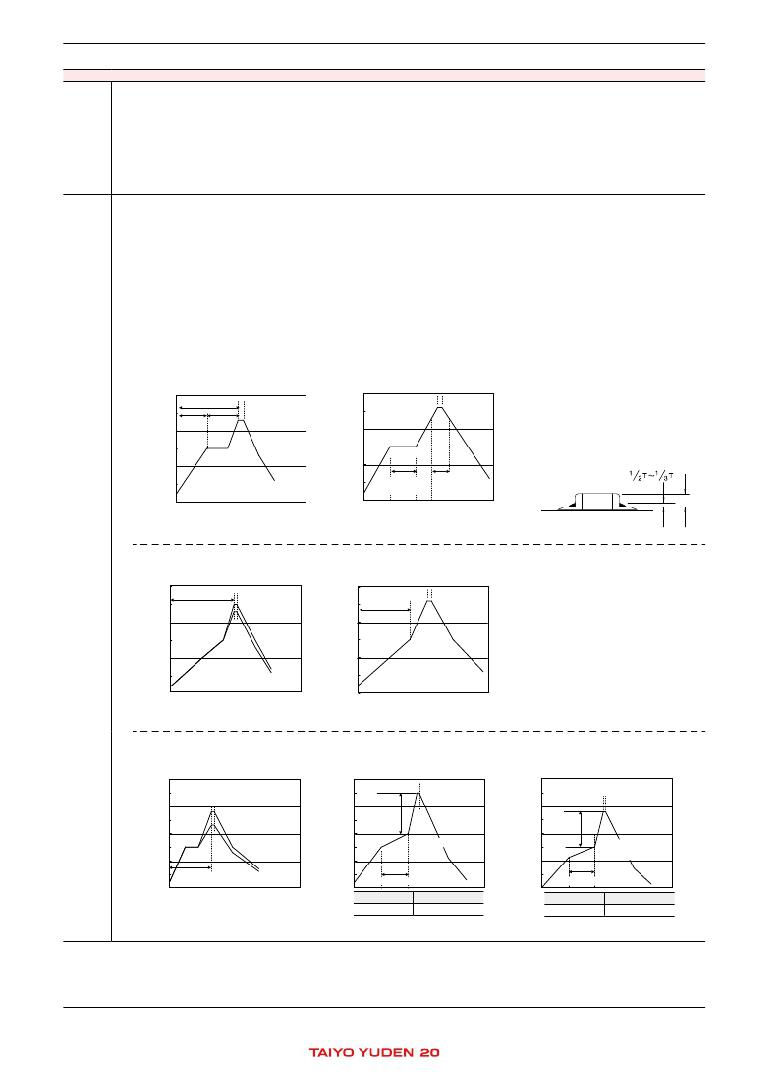
�[� Re?ow� soldering� ]�
�【� Recommended� conditions� for� eutectic� soldering� 】�
�200�
�Slow�
�cooling�
�【� Recommended� condition� for� Pb-free� soldering� 】�
�Slow� cooling�
�cooling�
�100�
�200� 60sec.� Min.�
�Heating� above�
�300�
�300�
�200�
�200�
�Preheating�
�60sec.� 60sec.�
�Min.� Min.�
�Peak� 260� ℃� Max.�
�230� ℃�
�Within� 10sec.�
�Within� 10� sec.�
�Slow�
�cooling�
�300�
�0�
�Preheating� 150� ℃�
�Peak� 260� ℃� Max.�
�Within� 10sec.�
�230� ℃�
�40sec.� Max.�
�Slow�
�cooling�
�100�
�100�
�Peak� 260� ℃� Max.� 100� 230� ~� 250� ℃�
�Preheating� 150� ℃�
�Heating� above� Within� 3sec.�
�230� ℃�
�230� ℃�
�Preheating� 150� ℃�
�60sec.� Min.� 120sec.� Min.� 230� ℃�
�200� 0� 0�
�40sec.� Max.�
�0�
�Slow� cooling�
�Caution�
�①� The� 300�
�ideal� condition� is� to� have� solder� mass� (� ?llet� )� controlled� 300� 1/2� to� 1/3� of� the� thickness� of� a� capacitor.�
�to�
�②� Because� excessive� dwell� times� can� adversely� affect� solderability,� soldering� duration� 230� ~� 250� ℃�
�100� 230� ~� 250� ℃� 100�
�close� to� recommended� times� Within� possible.�
�as�
�Within� 3sec.�
�Heating� above�
�Preheating�
�120sec.� Min.� 150� ℃� 230� ℃�
�200�
�60sec.� Min.�
�[� Wave� soldering� ]� 40sec.� Max.� 200�
�Slow� cooling�
�Slow� cooling�
�【� Recommended� conditions� for� eutectic� soldering� 】�
�【� Recommended� condition� for� Pb-free� soldering� 】�
�100�
�100�
�Preheating�
�Technical�
�consider-�
�ations�
�300� 300�
�100�
�300�
�0� 0�
�Preheating� Within� 3sec.�
�120sec.� Min.�
�Preheating�
�40sec.� Max.� 200� 60sec.� Min.�
�Slow� 0�
�cooling�
�300� 300�
�Preheating� 150� ℃� Preheating� Heating� above�
�200� 120sec.� Min.�
�shall� be� kept� as�
�Slow� cooling�
�230� ~� 250� ℃� 100� Peak� 260� ℃� Max.�
�Within� 3sec.� Within� 10sec.�
�Solder�
�Capacitor�
�PC� board�
�T�
�200� 0� 0�
�Slow� cooling�
�Preheating�
�150� ℃�
�300�
�Peak� 260� ℃� Max.�
�Within� 10sec.�
�120sec.� Min.�
�200�
�Slow�
�Preheating� cooling�
�Preheating�
�cooling�
�150� ℃�
�150� ℃�
�①� Wave� soldering� must� not� be� applied� to� capacitors� designated� as� for� re?ow� soldering� only.�
�Peak� 260� ℃� Max.�
�100�
�Within� 3� sec.�
�120sec.� Min.�
�[� Hand� 200� 0� 0�
�Slow�
�【� Recommended� conditions� for� eutectic� soldering� 】�
�【� Recommended� condition� for� Pb-free� soldering� 】�
�Preheating�
�150� ℃�
�400�
�Peak� 350� ℃� Max.�
�Peak� 350� ℃� Max.�
�230� ~� 280� ℃� Within� 3sec.�
�Within� 3� 3� sec.�
�Within� sec.�
�100�
�300�
�300�
�300�
�300�
�0�
�Slow� cooling�
�Slow� cooling�
�0�
�200�
�Preheating� cooling�
�Slow�
�400�
�400�
�150� Peak� 350� ℃� Max.�
�230� ~� 280� ℃�
�Within� 3sec.�
�100�
�Preheating� Min.�
�⊿� T�
�0�
�Slow� cooling�
�⊿� T�
�400�
�300�
�200�
�100�
�0� 0�
�Peak� 280� ℃� Max.�
�Peak� 280� ℃� Max.�
�150� ℃� Peak� 350� ℃� Max.�
�Within� 3sec.�
�⊿� T�
�Slow� cooling�
�Slow� cooling�
�Preheating�
�60sec.� Min.�
�⊿� T�
�120sec.� Min.� 120sec.� Min.�
�200�
�0� Slow�
�cooling�
�300�
�100� Peak� 260� ℃� Max.� 100�
�Within� 10sec.�
�120sec.� Min.�
�200�
�0� Slow� 0�
�cooling�
�Caution� Preheating�
�100�
�230� ~� 280� ℃�
�Within� 10sec.�
�300�
�soldering� ]�
�0�
�cooling� 200�
�400� 400� Slow� cooling�
�100� 230� ~� 280� ℃�
�Within� 3sec.�
�Within� 3� sec.�
�⊿� ⊿� T� T�
�300� Preheating�
�60sec.� Min.�
�200� 200�
�Slow� cooling� Preheating�
�100� 100�
�Within� 3� sec.�
�300� Preheating� 300�
�60sec.� Min.� 60sec.� Min.�
�0� 0� 60sec.� Min.�
�200� 200�
�⊿� T� ≦�
�Slow� cooling� 316type� or� less� Preheating� 150� ℃�
�a� of� 1.0�
�Caution� 150� ℃� Min.�
�①� Use� 100� 50W� soldering� iron� with� a� maximum� tip� diameter� 100� mm.�
�②� The� soldering� iron� shall� not� directly� touch� capacitors.�
�Preheating�
�60sec.� Min.� 60sec.� Min.�
�0� 0�
�400�
�300�
�200�
�400�
�100�
�300�
�0�
�200�
�400�
�100�
�300�
�200�
�100�
�0�
�0�
�Peak� 350� ℃� Max.�
�Within� 3sec.�
�⊿� T�
�Slow� cooling�
�Preheating�
�Within� 3sec.�
�60sec.� Min.�
�⊿� T� Slow� cooling�
�Preheating�
�℃� ℃� Min.� 280�
�150� Peak� Min.� ℃� Max.�
�Within� 3sec.�
�60sec.� Min.�
�Slow� cooling�
�⊿� T�
�⊿� T�
�325type� or� more� Preheating� ≦� 130� ℃�
�150� ℃� Min.�
�60sec.� Min.�
�400�
�300�
�200�
�400�
�100�
�300�
�0�
�200�
�100�
�0�
�⊿� T�
�60sec.� M�
�⊿� T�
�60sec.�
�*� This� catalog� contains� the� typical� speci� ?cation� only� due� to� the� limitation� of� space.� When� you� consider� the� purchase� of� our� products,� please� check� our� speci� ?cation.�
�For� details� of� each� product� (characteristics� graph,� reliability� information,� precautions� for� use,� and� so� on),� see� our� Web� site� (http://www.ty-top.com/)� or� CD� catalogs.�
�mlcc_prec-P3�
�12�
�mlcc_prec_e-01�
�相关PDF资料 |
PDF描述 |
|---|---|
| 3361P-1-202G | TRIMMER 2K OHM 0.5W SMD |
| LD6806F/36P,115 | IC REG LDO 200MA 3.6V 6XSON |
| LD6806F/33P,115 | IC REG LDO 200MA 3.3V 6XSON |
| 3361P-1-102G | TRIMMER 1K OHM 0.5W SMD |
| LD6806F/30P,115 | IC REG LDO 200MA 3.0V 6XSON |
相关代理商/技术参数 |
参数描述 |
|---|---|
| AD7846BPZ | 功能描述:IC DAC 16BIT LC2MOS VOUT 28PLCC RoHS:是 类别:集成电路 (IC) >> 数据采集 - 数模转换器 系列:- 标准包装:1 系列:- 设置时间:4.5µs 位数:12 数据接口:串行,SPI? 转换器数目:1 电压电源:单电源 功率耗散(最大):- 工作温度:-40°C ~ 125°C 安装类型:表面贴装 封装/外壳:8-SOIC(0.154",3.90mm 宽) 供应商设备封装:8-SOICN 包装:剪切带 (CT) 输出数目和类型:1 电压,单极;1 电压,双极 采样率(每秒):* 其它名称:MCP4921T-E/SNCTMCP4921T-E/SNRCTMCP4921T-E/SNRCT-ND |
| AD7846BQ | 制造商:未知厂家 制造商全称:未知厂家 功能描述:16-Bit Digital-to-Analog Converter |
| AD7846JN | 功能描述:IC DAC 16BIT LC2MOS VOUT 28-DIP RoHS:否 类别:集成电路 (IC) >> 数据采集 - 数模转换器 系列:- 产品培训模块:Lead (SnPb) Finish for COTS Obsolescence Mitigation Program 标准包装:1,000 系列:- 设置时间:1µs 位数:8 数据接口:串行 转换器数目:8 电压电源:双 ± 功率耗散(最大):941mW 工作温度:0°C ~ 70°C 安装类型:表面贴装 封装/外壳:24-SOIC(0.295",7.50mm 宽) 供应商设备封装:24-SOIC W 包装:带卷 (TR) 输出数目和类型:8 电压,单极 采样率(每秒):* |
| AD7846JNZ | 功能描述:IC DAC 16BIT LC2MOS VOUT 28-DIP RoHS:是 类别:集成电路 (IC) >> 数据采集 - 数模转换器 系列:- 标准包装:1 系列:- 设置时间:4.5µs 位数:12 数据接口:串行,SPI? 转换器数目:1 电压电源:单电源 功率耗散(最大):- 工作温度:-40°C ~ 125°C 安装类型:表面贴装 封装/外壳:8-SOIC(0.154",3.90mm 宽) 供应商设备封装:8-SOICN 包装:剪切带 (CT) 输出数目和类型:1 电压,单极;1 电压,双极 采样率(每秒):* 其它名称:MCP4921T-E/SNCTMCP4921T-E/SNRCTMCP4921T-E/SNRCT-ND |
| AD7846JNZ | 制造商:Analog Devices 功能描述:IC 12-BIT DAC |
发布紧急采购,3分钟左右您将得到回复。