- 您现在的位置:买卖IC网 > PDF目录10331 > AD7927WYRUZ-REEL7 (Analog Devices Inc)IC ADC 12BIT 8CH W/SEQ 20TSSOP PDF资料下载
参数资料
| 型号: | AD7927WYRUZ-REEL7 |
| 厂商: | Analog Devices Inc |
| 文件页数: | 4/28页 |
| 文件大小: | 0K |
| 描述: | IC ADC 12BIT 8CH W/SEQ 20TSSOP |
| 标准包装: | 1 |
| 位数: | 12 |
| 采样率(每秒): | 200k |
| 数据接口: | DSP,MICROWIRE?,QSPI?,串行,SPI? |
| 转换器数目: | 1 |
| 功率耗散(最大): | 7.5mW |
| 电压电源: | 单电源 |
| 安装类型: | 表面贴装 |
| 封装/外壳: | 20-TSSOP(0.173",4.40mm 宽) |
| 供应商设备封装: | 20-TSSOP |
| 包装: | 标准包装 |
| 输入数目和类型: | 8 个单端,单极 |
| 其它名称: | AD7927WYRUZ-REEL7DKR |
第1页第2页第3页当前第4页第5页第6页第7页第8页第9页第10页第11页第12页第13页第14页第15页第16页第17页第18页第19页第20页第21页第22页第23页第24页第25页第26页第27页第28页
AD7927
Data Sheet
Rev. D | Page 12 of 28
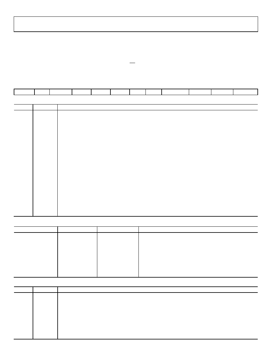
CONTROL REGISTER
The control register on the AD7927 is a 12-bit, write-only register. Data is loaded from the DIN pin of the AD7927 on the falling edge of
SCLK. The data is transferred on the DIN line at the same time that the conversion result is read from the part. The data transferred on
the DIN line corresponds to the AD7927 configuration for the next conversion. This requires 16 serial clocks for every data transfer. Only
the information provided on the first 12 falling clock edges (after CS falling edge) is loaded to the control register. MSB denotes the first
bit in the data stream. The bit functions are outlined in Table 5.
Table 5. Control Register Bit Functions
MSB
LSB
WRITE
SEQ
DONTC
ADD2
ADD1
ADD0
PM1
PM0
SHADOW
DONTC
RANGE
CODING
Table 6. Control Register Bit Function Description
Bit
Mnemonic
Description
11
WRITE
The value written to this bit of the control register determines whether the following 11 bits are loaded to
the control register. If this bit is a 1, the following 11 bits are written to the control register; if it is a 0, then the
remaining 11 bits are not loaded to the control register and it remains unchanged.
10
SEQ
The SEQ bit in the control register is used in conjunction with the SHADOW bit to control the use of the sequencer
function and access the shadow register (see Table 10).
9
DONTC
Don’t care.
8 to 6
ADD2 to
ADD0
These three address bits are loaded at the end of the present conversion and select which analog input channel
is to be converted in the next serial transfer, or they may select the final channel in a consecutive sequence as
described in Table 9. The selected input channel is decoded as shown in Table 7. The address bits corresponding
to the conversion result are also output on DOUT prior to the 12 bits of data (see the Serial Interface section). The
next channel to be converted on is selected by the mux on the 14th SCLK falling edge.
5, 4
PM1, PM0
Power Management Bits. These two bits decode the mode of operation of the AD7927 as shown in Table 8.
3
SHADOW
The SHADOW bit in the control register is used in conjunction with the SEQ bit to control the use of the sequencer
function and access the shadow register (see Table 10).
2
DONTC
Don’t care.
1
RANGE
This bit selects the analog input range to be used on the AD7927. If it is set to 0, the analog input range extends
from 0 V to 2 × REFIN. If it is set to 1, the analog input range extends from 0 V to REFIN (for the next conversion). For
the 0 V to 2 × REFIN range, AVDD = 4.75 V to 5.25 V.
0
CODING
This bit selects the type of output coding the AD7927 uses for the conversion result. If this bit is set to 0, the
output coding for the part is twos complement. If this bit is set to 1, the output coding from the part is straight
binary (for the next conversion).
Table 7. Channel Selection
ADD2
ADD1
ADD0
Analog Input Channel
0
VIN0
0
1
VIN1
0
1
0
VIN2
0
1
VIN3
1
0
VIN4
1
0
1
VIN5
1
0
VIN6
1
VIN7
Table 8. Power Mode Selection
PM1
PM0
Mode
1
Normal Operation. In this mode, the AD7927 remains in full power mode, regardless of the status of any of the
logic inputs. This mode allows the fastest possible throughput rate from the AD7927.
1
0
Full Shutdown. In this mode, the AD7927 is in full shutdown mode with all circuitry on the AD7927 powering
down. The AD7927 retains the information in the control register while in full shutdown. The part remains in full
shutdown until these bits are changed.
0
1
Auto Shutdown. In this mode, the AD7927 automatically enters full shutdown mode at the end of each conversion
when the control register is updated. Wake-up time from full shutdown is 1 μs and the user should ensure that 1
μs has elapsed before attempting to perform a valid conversion on the part in this mode.
0
Invalid Selection. This configuration is not allowed.
相关PDF资料 |
PDF描述 |
|---|---|
| D38999/20WE8BA | CONN HSG RCPT 8POS WALL MT SCKT |
| D38999/26WG39SNLC | CONN HSG PLUG 39POS STRGHT SCKT |
| AD7789BRMZ-REEL | IC ADC 24BIT SIGMA-DELTA 10MSOP |
| D38999/26WC98SBLC | CONN HSG PLUG 10POS STRGHT SCKT |
| AD7790BRMZ-REEL | IC ADC 16BIT SIGMA-DELTA 10-MSOP |
相关代理商/技术参数 |
参数描述 |
|---|---|
| AD7928 | 制造商:AD 制造商全称:Analog Devices 功能描述:8-Channel, 1 MSPS, 8-/10-/12-Bit ADCs with Sequencer in 20-Lead TSSOP |
| AD7928BRU | 制造商:Analog Devices 功能描述:IC 12BIT ADC SMD 7928 TSSOP8 |
| AD7928BRU-REEL | 制造商:Analog Devices 功能描述:ADC Single SAR 1Msps 12-bit Serial 20-Pin TSSOP T/R |
| AD7928BRU-REEL7 | 制造商:Analog Devices 功能描述:ADC Single SAR 1Msps 12-bit Serial 20-Pin TSSOP T/R 制造商:Rochester Electronics LLC 功能描述:12-BIT 8, CH 1 MSPS ADC I.C. - Tape and Reel |
| AD7928BRUZ | 功能描述:IC ADC 12BIT 8CH 1MSPS 20-TSSOP RoHS:是 类别:集成电路 (IC) >> 数据采集 - 模数转换器 系列:- 标准包装:1 系列:microPOWER™ 位数:8 采样率(每秒):1M 数据接口:串行,SPI? 转换器数目:1 功率耗散(最大):- 电压电源:模拟和数字 工作温度:-40°C ~ 125°C 安装类型:表面贴装 封装/外壳:24-VFQFN 裸露焊盘 供应商设备封装:24-VQFN 裸露焊盘(4x4) 包装:Digi-Reel® 输入数目和类型:8 个单端,单极 产品目录页面:892 (CN2011-ZH PDF) 其它名称:296-25851-6 |
发布紧急采购,3分钟左右您将得到回复。