- 您现在的位置:买卖IC网 > PDF目录20979 > TH3B156M6R3E1800 (Vishay Sprague)CAP TANT 15UF 6.3V 20% 1411 PDF资料下载
参数资料
| 型号: | TH3B156M6R3E1800 |
| 厂商: | Vishay Sprague |
| 文件页数: | 12/18页 |
| 文件大小: | 0K |
| 描述: | CAP TANT 15UF 6.3V 20% 1411 |
| 标准包装: | 2,000 |
| 系列: | TANTAMOUNT® TH3 |
| 电容: | 15µF |
| 电压 - 额定: | 6.3V |
| 容差: | ±20% |
| ESR(等效串联电阻): | 1.8 欧姆 |
| 类型: | 模制 |
| 工作温度: | -55°C ~ 150°C |
| 安装类型: | 表面贴装 |
| 封装/外壳: | 1411(3528 公制) |
| 尺寸/尺寸: | 0.138" L x 0.110" W(3.50mm x 2.80mm) |
| 高度 - 座高(最大): | 0.083"(2.10mm) |
| 制造商尺寸代码: | B |
| 特点: | 高可靠性 |
| 包装: | 带卷 (TR) |
�� �
�
�Molded� Guide�
�www.vishay.com�
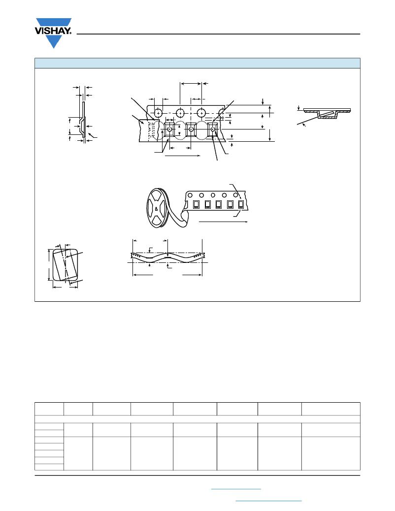
�PLASTIC� TAPE� AND� REEL� PACKAGING� in� inches� [millimeters]�
�0.157� ±� 0.004�
�Vishay� Sprague�
�Embossment�
�Tape� thickness�
�0.014�
�[0.35]�
�MAX.�
�Deformation�
�between�
�embossments�
�0.059� +� 0.004� -� 0.0�
�[1.5� +� 0.10� -� 0.0]�
�[4.0� ±� 0.10]�
�10� pitches� cumulative�
�tolerance� on� tape�
�±� 0.008� [0.200]�
�0.079� ±� 0.002�
�[2.0� ±� 0.05]�
�0.069� ±� 0.004�
�[1.75� ±� 0.10]�
�Top�
�B� 1� MAX.�
�(Note� 6)�
�K� 0�
�Top�
�cover�
�tape�
�A� 0�
�B� 0�
�0.030� [0.75]�
�MIN.� (Note� 3)�
�0.030� [0.75]�
�F�
�W�
�20°�
�Maxim� um�
�component�
�rotation�
�cover�
�tape�
�MIN.� (Note� 4)�
�(Side� or� front� sectional� view)�
�P� 1�
�For� tape� feeder�
�reference� only�
�including� draft.�
�0.004� [0.1]�
�MAX.�
�Center� lines�
�of� cavity�
�USER� DIRECTION� OF� FEED�
�Maximum�
�D� 1� MIN.� for� components�
�0.079� x� 0.047� [2.0� x� 1.2]� and� larger� .�
�(Note� 5)�
�Concentric� around� B� 0�
�(Note� 5)�
�cavity� size�
�(Note� 1)�
�Cathode� (-)�
�Anode� (+)�
�Direction� of� Feed�
�B� 0�
�A� 0�
�(Top� view)�
�20°� maximum�
�component� rotation�
�Typical�
�component�
�cavity�
�center� line�
�Typical�
�component�
�center� line�
�3.937� [100.0]�
�0.039� [1.0]�
�MAX.�
�Tape�
�0.039� [1.0]�
�MAX.�
�0.9843� [250.0]�
�Camber�
�(top� view)�
�Allowable� camber� to� be� 0.039/3.937� [1/100]�
�non-cumulative� over� 9.843� [250.0]�
�Tape� and� Reel� Specifications:� All� case� sizes� are� available�
�on� plastic� embossed� tape� per� EIA-481.� Standard� reel�
�diameter� is� 7"� [178� mm],� 13"� [330� mm]� reels� are� available� and�
�recommended� as� the� most� cost� effective� packaging� method.�
�The� most� efficient� packaging� quantities� are� full� reel�
�increments� on� a� given� reel� diameter.� The� quantities� shown�
�allow� for� the� sealed� empty� pockets� required� to� be� in�
�conformance� with� EIA-481.� Reel� size� and� packaging�
�orientation� must� be� specified� in� the� Vishay� Sprague� part�
�number.�
�Notes�
�?� Metric� dimensions� will� govern.� Dimensions� in� inches� are� rounded� and� for� reference� only.�
�(1)� A� 0� ,� B� 0� ,� K� 0� ,� are� determined� by� the� maximum� dimensions� to� the� ends� of� the� terminals� extending� from� the� component� body� and/or� the� body�
�dimensions� of� the� component.� The� clearance� between� the� ends� of� the� terminals� or� body� of� the� component� to� the� sides� and� depth� of� the�
�cavity� (A� 0� ,� B� 0� ,� K� 0� )� must� be� within� 0.002"� (0.05� mm)� minimum� and� 0.020"� (0.50� mm)� maximum.� The� clearance� allowed� must� also� prevent�
�rotation� of� the� component� within� the� cavity� of� not� more� than� 20°.�
�(2)� Tape� with� components� shall� pass� around� radius� “R”� without� damage.� The� minimum� trailer� length� may� require� additional� length� to� provide�
�“R”� minimum� for� 12� mm� embossed� tape� for� reels� with� hub� diameters� approaching� N� minimum.�
�(3)� This� dimension� is� the� flat� area� from� the� edge� of� the� sprocket� hole� to� either� outward� deformation� of� the� carrier� tape� between� the� embossed�
�cavities� or� to� the� edge� of� the� cavity� whichever� is� less.�
�(4)� This� dimension� is� the� flat� area� from� the� edge� of� the� carrier� tape� opposite� the� sprocket� holes� to� either� the� outward� deformation� of� the� carrier�
�tape� between� the� embossed� cavity� or� to� the� edge� of� the� cavity� whichever� is� less.�
�(5)� The� embossed� hole� location� shall� be� measured� from� the� sprocket� hole� controlling� the� location� of� the� embossement.� Dimensions� of�
�embossement� location� shall� be� applied� independent� of� each� other.�
�(6)� B� 1� dimension� is� a� reference� dimension� tape� feeder� clearance� only.�
�CASE�
�CODE�
�TAPE�
�SIZE�
�B� 1�
�(MAX.)�
�D� 1�
�(MIN.)�
�F�
�K� 0�
�(MAX.)�
�P� 1�
�W�
�293D� -� 593D� -� 893D� -� TR3� -� TH3� -� TF3� -� TP3� -� 793DE/793DX/CTC3/CTC4�
�A�
�B�
�8� mm�
�0.165�
�[4.2]�
�0.039�
�[1.0]�
�0.138� ±� 0.002�
�[3.5� ±� 0.05]�
�0.094�
�[2.4]�
�0.157� ±� 0.004�
�[4.0� ±� 1.0]�
�0.315� ±� 0.012�
�[8.0� ±� 0.30]�
�C�
�D�
�E�
�V�
�12� mm�
�0.32�
�[8.2]�
�0.059�
�[1.5]�
�0.217� ±� 0.00�
�[5.5� ±� 0.05]�
�0.177�
�[4.5]�
�0.315� ±� 0.004�
�[8.0� ±� 1.0]�
�0.472� ±� 0.012�
�[12.0� ±� 0.30]�
�W�
�Revision:� 03-Feb-14�
�5�
�Document� Number:� 40074�
�For� technical� questions,� contact:� tantalum@vishay.com�
�THIS� DOCUMENT� IS� SUBJECT� TO� CHANGE� WITHOUT� NOTICE.� THE� PRODUCTS� DESCRIBED� HEREIN� AND� THIS� DOCUMENT�
�ARE� SUBJECT� TO� SPECIFIC� DISCLAIMERS,� SET� FORTH� AT� www.vishay.com/doc?91000�
�相关PDF资料 |
PDF描述 |
|---|---|
| TH3B156K6R3E1800 | CAP TANT 15UF 6.3V 10% 1411 |
| MUR2100ERLG | DIODE ULTRA FAST 2A 1KV DO-41 |
| RPP30-2412SW | CONV DC/DC 30W SNGL 12V OUT |
| P51-1000-A-Y-I36-4.5V-000-000 | SENSOR 1000PSI 7/16-20-2B 4.5V |
| RPP20-2424SW-B | CONV DC/DC 20W 9-36VIN 24V OUT |
相关代理商/技术参数 |
参数描述 |
|---|---|
| AD7940BRM-REEL7 | 功能描述:IC ADC 14BIT UNIPOLAR 8-MSOP RoHS:否 类别:集成电路 (IC) >> 数据采集 - 模数转换器 系列:- 标准包装:1,000 系列:- 位数:16 采样率(每秒):45k 数据接口:串行 转换器数目:2 功率耗散(最大):315mW 电压电源:模拟和数字 工作温度:0°C ~ 70°C 安装类型:表面贴装 封装/外壳:28-SOIC(0.295",7.50mm 宽) 供应商设备封装:28-SOIC W 包装:带卷 (TR) 输入数目和类型:2 个单端,单极 |
| AD7940BRMZ | 功能描述:IC ADC 14BIT UNIPOLAR 8-MSOP RoHS:是 类别:集成电路 (IC) >> 数据采集 - 模数转换器 系列:- 其它有关文件:TSA1204 View All Specifications 标准包装:1 系列:- 位数:12 采样率(每秒):20M 数据接口:并联 转换器数目:2 功率耗散(最大):155mW 电压电源:模拟和数字 工作温度:-40°C ~ 85°C 安装类型:表面贴装 封装/外壳:48-TQFP 供应商设备封装:48-TQFP(7x7) 包装:Digi-Reel® 输入数目和类型:4 个单端,单极;2 个差分,单极 产品目录页面:1156 (CN2011-ZH PDF) 其它名称:497-5435-6 |
| AD7940BRMZ-REEL7 | 功能描述:IC ADC 14BIT 100KSPS 8MSOP RoHS:是 类别:集成电路 (IC) >> 数据采集 - 模数转换器 系列:- 标准包装:1,000 系列:- 位数:16 采样率(每秒):45k 数据接口:串行 转换器数目:2 功率耗散(最大):315mW 电压电源:模拟和数字 工作温度:0°C ~ 70°C 安装类型:表面贴装 封装/外壳:28-SOIC(0.295",7.50mm 宽) 供应商设备封装:28-SOIC W 包装:带卷 (TR) 输入数目和类型:2 个单端,单极 |
| AD7940-DBRD | 功能描述:BOARD EVAL FOR AD7940 STAMP SPI RoHS:否 类别:编程器,开发系统 >> 评估板 - 模数转换器 (ADC) 系列:- 产品培训模块:Obsolescence Mitigation Program 标准包装:1 系列:- ADC 的数量:1 位数:12 采样率(每秒):94.4k 数据接口:USB 输入范围:±VREF/2 在以下条件下的电源(标准):- 工作温度:-40°C ~ 85°C 已用 IC / 零件:MAX11645 已供物品:板,软件 |
| AD7942 | 制造商:AD 制造商全称:Analog Devices 功能描述:16-Bit, +/-0.65 LSB INL, 500 kSPS PulSAR Differential ADC in MSOP/QFN |
发布紧急采购,3分钟左右您将得到回复。