- 您现在的位置:买卖IC网 > PDF目录43975 > LK1501-7PD2B2 1-OUTPUT 150 W AC-DC REG PWR SUPPLY MODULE PDF资料下载
参数资料
| 型号: | LK1501-7PD2B2 |
| 元件分类: | 电源模块 |
| 英文描述: | 1-OUTPUT 150 W AC-DC REG PWR SUPPLY MODULE |
| 封装: | METAL, CASE K02, MODULE |
| 文件页数: | 2/26页 |
| 文件大小: | 601K |
| 代理商: | LK1501-7PD2B2 |
Cassette Style
150 Watt AC-DC Converters
K Series
Edition 01/01.2001
10/26
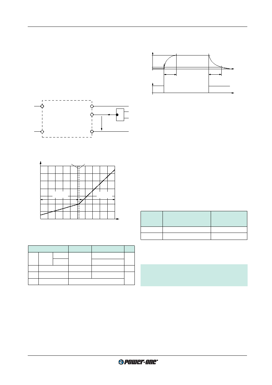
0
t
0
Inhibit
1
0.1
1
Uo/Uo nom
tr
tf
06001
Fig. 15
Output response as a function of inhibit control
Auxiliary Functions
i Inhibit for Remote On and Off
Note: With open i input: Output is disabled (
Uo = off).
The outputs of the module may be enabled or disabled by
means of a logic signal (TTL, CMOS, etc.) applied between
the inhibit input i and the negative pin of output 1 (Vo1–). In
systems with several units, this feature can be used, for ex-
ample, to control the activation sequence of the converters.
If the inhibit function is not required, connect the inhibit pin
18 to pin 14 to enable the outputs (active low logic, fail
safe). For output response refer to:
Hold-up Time and Out-
put Response.
Vi+
Vi–
Vo–
i
Vo+
Iinh
Uinh
06031
1.6
0.8
0
–0.8
–50
Uinh [V]
Iinh [mA]
–30
0
–10
10
30
50
2.0
1.2
0.4
–0.4
Uinh = 0.8 V
Uo = on
Uo = off
Uinh = 2.4 V
06032
Fig. 13
Definition of Uinh and Iinh.
Fig. 14
Typical inhibit current Iinh versus inhibit voltage Uinh
Table 5: Inhibit characteristics
Characteristic
Conditions
min
typ
max Unit
Uinh Inhibit
Uo = on
Ui min…Ui max
–50
0.8
V
voltage
Uo = off
2.4
50
Iinh
Inhibit current
Uinh = 0
–400
A
tr
Rise time
30
ms
tf
Fall time
depending on
Io
Sense Lines
(Only for single output units 5.1 V, 12 V, 15 V, 24 V)
This feature enables for compensation of voltage drops
across the connector contacts and if necessary, across the
load lines. If the sense lines are connected at the load
rather than directly at the connector, the user should ensure
that
Uo max (between Vo1+ and Vo1–) is not exceeded. We
recommend connecting the sense lines directly at the fe-
male connector.
For further information, please refer to:
Application Notes .
To ensure correct operation, both sense lines (S+ and S–)
should be connected to their respective power outputs
(Vo1+ and Vo1–) and the voltage difference between any
sense line and its respective power output pin (as meas-
ured on the connector) should not exceed the following val-
ues:
Table 6: Maximum Voltage compensation allowed using
sense lines
Output
Total voltage difference
Voltage difference
voltage
between sense lines and
between
their respective outputs
Vo– and S–
5.1 V
<0.5 V
<0.25 V
12 V, 15 V
<1.0 V
<0.25 V
If the output voltages are increased above
Uo nom via R-in-
put control, option P setting, remote sensing or option T, the
output currents must be reduced accordingly so that
Po nom is not exceeded.
Important: The output terminals Vo1+ and Vo1– must
always be connected to the load before connecting the
sense lines S+ and S–, otherwise the unit will be dam-
aged.
相关PDF资料 |
PDF描述 |
|---|---|
| LK1501-9PDDB1 | 1-OUTPUT 150 W AC-DC REG PWR SUPPLY MODULE |
| LK1601-7ERD0TB2 | 1-OUTPUT 150 W AC-DC REG PWR SUPPLY MODULE |
| LK1601-7ERDDB2 | 1-OUTPUT 150 W AC-DC REG PWR SUPPLY MODULE |
| LK1601-7PD9TB2 | 1-OUTPUT 150 W AC-DC REG PWR SUPPLY MODULE |
| LK1601-7PDDB1 | 1-OUTPUT 150 W AC-DC REG PWR SUPPLY MODULE |
相关代理商/技术参数 |
参数描述 |
|---|---|
| EPM7512AEFC256-7N | 功能描述:CPLD - 复杂可编程逻辑器件 CPLD - MAX 7000 512 Macro 212 IOs RoHS:否 制造商:Lattice 系列: 存储类型:EEPROM 大电池数量:128 最大工作频率:333 MHz 延迟时间:2.7 ns 可编程输入/输出端数量:64 工作电源电压:3.3 V 最大工作温度:+ 90 C 最小工作温度:0 C 封装 / 箱体:TQFP-100 |
| EPM7512AEFI25610 | 制造商:ALTERA 功能描述:NEW |
| EPM7512AEFI256-10 | 功能描述:CPLD - 复杂可编程逻辑器件 CPLD - MAX 7000 512 Macro 212 IOs RoHS:否 制造商:Lattice 系列: 存储类型:EEPROM 大电池数量:128 最大工作频率:333 MHz 延迟时间:2.7 ns 可编程输入/输出端数量:64 工作电源电压:3.3 V 最大工作温度:+ 90 C 最小工作温度:0 C 封装 / 箱体:TQFP-100 |
| EPM7512AEFI256-10N | 功能描述:CPLD - 复杂可编程逻辑器件 CPLD - MAX 7000 512 Macro 212 IOs RoHS:否 制造商:Lattice 系列: 存储类型:EEPROM 大电池数量:128 最大工作频率:333 MHz 延迟时间:2.7 ns 可编程输入/输出端数量:64 工作电源电压:3.3 V 最大工作温度:+ 90 C 最小工作温度:0 C 封装 / 箱体:TQFP-100 |
| EPM7512AEQC20810 | 制造商:ALTERA 功能描述:* |
发布紧急采购,3分钟左右您将得到回复。