- 您现在的位置:买卖IC网 > PDF目录11402 > FGG.0B.304.CLAD52Z (LEMO)CONN PLUG 4POS STRGHT PIN SOLDER PDF资料下载
参数资料
| 型号: | FGG.0B.304.CLAD52Z |
| 厂商: | LEMO |
| 文件页数: | 179/186页 |
| 文件大小: | 0K |
| 描述: | CONN PLUG 4POS STRGHT PIN SOLDER |
| 产品培训模块: | B Series Multi-Pin Connectors |
| 标准包装: | 100 |
| 系列: | 0B |
| 连接器类型: | 插头,公引脚 |
| 位置数: | 4 |
| 外壳尺寸 - 插件: | 304 |
| 安装类型: | 自由悬挂 |
| 端子: | 焊杯 |
| 紧固型: | 推挽式 |
| 方向: | G |
| 外壳材料,表面处理: | 黄铜,镍上镀铬 |
| 触点表面涂层: | 金 |
| 特点: | 屏蔽 |
| 包装: | 散装 |
| 额定电流: | 7A |
| 工作温度: | -55°C ~ 250°C |
| 配套产品: | 1124-1037-ND - CONN RCPT 4POS PNL MNT SKT W/NUT |
| 相关产品: | 1124-1252-ND - BOOT STRAIN RELIEF 11MM DIAMETER 1124-1093-ND - STRAIN RELIEF 4.5MM DIA BLACK 1124-1092-ND - STRAIN RELIEF 4.5MM DIA GREEN 1124-1091-ND - STRAIN RELIEF 4.5MM DIA RED 1124-1090-ND - STRAIN RELIEF 4.5MM DIA BLACK 1124-1089-ND - STRAIN RELIEF 4.5MM DIA YELLOW 1124-1088-ND - STRAIN RELIEF 4.5MM DIA WHITE 1124-1087-ND - STRAIN RELIEF 4.0MM DIA RED 1124-1086-ND - STRAIN RELIEF 4.0MM DIA BLACK 1124-1085-ND - STRAIN RELIEF 4.0MM DIA YELLOW 更多... |
| 其它名称: | 1124-1058 |
第1页第2页第3页第4页第5页第6页第7页第8页第9页第10页第11页第12页第13页第14页第15页第16页第17页第18页第19页第20页第21页第22页第23页第24页第25页第26页第27页第28页第29页第30页第31页第32页第33页第34页第35页第36页第37页第38页第39页第40页第41页第42页第43页第44页第45页第46页第47页第48页第49页第50页第51页第52页第53页第54页第55页第56页第57页第58页第59页第60页第61页第62页第63页第64页第65页第66页第67页第68页第69页第70页第71页第72页第73页第74页第75页第76页第77页第78页第79页第80页第81页第82页第83页第84页第85页第86页第87页第88页第89页第90页第91页第92页第93页第94页第95页第96页第97页第98页第99页第100页第101页第102页第103页第104页第105页第106页第107页第108页第109页第110页第111页第112页第113页第114页第115页第116页第117页第118页第119页第120页第121页第122页第123页第124页第125页第126页第127页第128页第129页第130页第131页第132页第133页第134页第135页第136页第137页第138页第139页第140页第141页第142页第143页第144页第145页第146页第147页第148页第149页第150页第151页第152页第153页第154页第155页第156页第157页第158页第159页第160页第161页第162页第163页第164页第165页第166页第167页第168页第169页第170页第171页第172页第173页第174页第175页第176页第177页第178页当前第179页第180页第181页第182页第183页第184页第185页第186页
�� �
�
�?�
�?�
�Contact� resistance� with� relation� to� the� number�
�of� mating� cyles�
�(measured� according� to� IEC� 60512-2� test� 2a)�
�Average� values� measured� after� the� mating� cycles� and� the�
�salt� spray� test� according� to� IEC� 60512-6� test� 11f.�
�Insulation� resistance� between� the� contacts�
�and� contact/shell�
�(measured� according� to� IEC� 60512-2� test� 3a)�
�A?�
�(mm)�
�Contact� resistance� (m� ?� )�
�1000� 3000� 5000�
�cycles� cycles� cycles�
�A?�
�(mm)�
�Contact� resistance� (m� ?� )�
�1000� 3000� 5000�
�cycles� cycles� cycles�
�Insulating� material�
�new�
�Multipole�
�PEEK�
�>� 10� 12� ?�
�Unipole�
�PTFE�
�>� 10� 12� ?�
�0.5�
�7.5�
�8.3�
�8.7�
�3.0�
�2.0�
�2.2�
�3.1�
�after� humidity� test� 1)�
�>� 10� 10� ?�
�>� 10� 10� ?�
�0.7�
�0.9�
�1.3�
�1.6�
�5.6�
�4.1�
�2.8�
�2.6�
�5.7�
�4.2�
�2.9�
�2.7�
�6.1�
�4.8�
�3.6�
�3.5�
�4.0�
�5.0�
�6.0�
�8.0�
�1.6�
�1.4�
�1.2�
�0.8�
�2.0�
�–�
�–�
�–�
�2.8�
�–�
�–�
�–�
�2.0�
�2.9�
�3.1�
�3.3�
�12.0�
�0.7�
�–�
�–�
�Note:� 1)� 21� days� at� 95%� RH� according� to� IEC� 60068-2-3.�
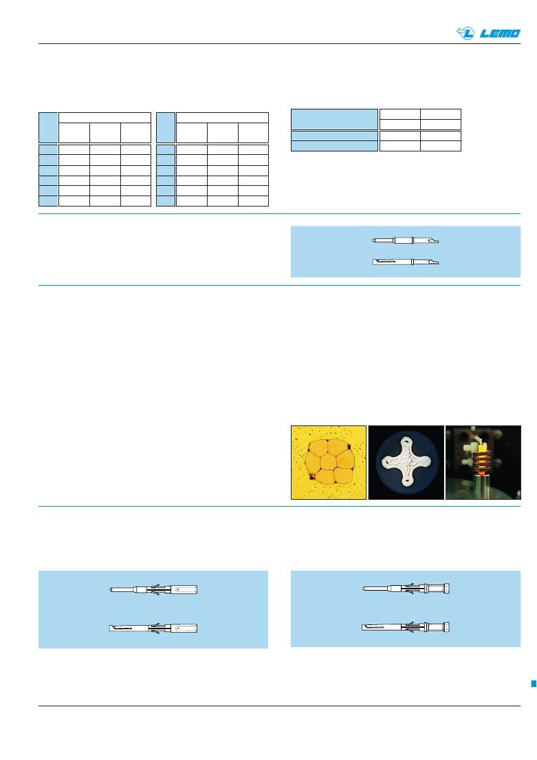
�Solder� contacts�
�The� conductor� bucket� of� these� contacts� is� machined� at� an�
����Crimp� contacts�
�The� square� form� crimp� method� is� used� (MIL-C-22520F,�
�class� I,� type� 2)� photo� 1� for� unipole� contacts.�
�For� multipole� contacts� the� standard� four� identer� crimp�
�method� is� used,� MIL-C-22520F,� class� I,� type� 1),� photo� 2.�
�The� crimp� method� requires� a� controlled� compression� to�
�obtain� a� symmetrical� deformation� of� the� conductor� strand� and�
�of� the� contact� material.� The� radial� hole� in� the� side� of� the� con-�
�tact� makes� it� possible� to� check� whether� the� conductor� is�
�correctly� positioned� within� the� contact.� A� good� crimping� is� char-�
�acterized� by� only� slightly� reduced� conductor� section� and�
�practically� no� gap.�
�Advantages� of� crimping�
�–� practical,� quick� contact� fixing� outside� the� insulator�
�–� possible� use� at� high� temperature�
�–� no� risk� of� heating� the� insulator� during� the� conductor-�
�contact� fixing�
�–� high� tensile� strength�
�Crimp� contacts� are� available� in� standard� version� (form� 1)� for�
�mounting� maximum� size� conductors.�
�For� some� dimensions,� these� crimp� contacts� can� be� pro-�
�duced� with� reduced� crimp� barrels� (form� 2)� for� mounting�
�reduced� size� conductors.�
�For� optimum� crimping� of� bronze� or� brass� contacts� they� are�
�annealed� to� relieve� internal� stress� and� reduce� material�
�1�
�2�
�3�
�hardening� during� the� crimping� process.�
�Only� the� crimping� zone� is� annealed� with� the� help� of� an�
�induction� heating� machine� designed� by� the� LEMO� Research�
�and� Development� Department� (see� photo� 3).�
�Crimp� contacts�
�The� crimp� contacts� can� be� with� two� forms:� a� standard� crimp�
�barrel� for� large� conductors� (see� fig.� 1)� or� with� a� reduced�
�crimp� barrel� for� smaller� conductors� (see� fig.� 2).�
�Fig.� 1�
�www.lemo.com�
�The� range� of� cable� dimensions� that� can� be� crimped� into�
��Fig.� 2�
�177�
�相关PDF资料 |
PDF描述 |
|---|---|
| FGG.0B.304.CLAD31Z | CONN PLUG 4POS STRGHT PIN SOLDER |
| VE-24Y-IY | CONVERTER MOD DC/DC 3.3V 33W |
| VE-24Y-IW | CONVERTER MOD DC/DC 3.3V 66W |
| VE-24X-IY | CONVERTER MOD DC/DC 5.2V 50W |
| VE-24X-EU-B1 | CONVERTER MOD DC/DC 5.2V 200W |
相关代理商/技术参数 |
参数描述 |
|---|---|
| FGG0B305CLAD56 | 制造商:LEMO connectors 功能描述:FICHE DROITE 0B 5CTS |
| FGG0B305CLAD56Z | 制造商:LEMO connectors 功能描述:CABLE TERMINATED, MALE, RF CONNECTOR, SOLDER, PLUG |
| FGG0B307CLAD52 | 制造商:LEMO connectors 功能描述:FICHE DROITE 0B 3CTS |
| FGG0B307CLAD56 | 制造商:LEMO connectors 功能描述:FICHE DROITE 0B 7CTS |
| FGG1B302CLAD42 | 制造商:LEMO connectors 功能描述:FICHE DROITE 1B 2CTS |
发布紧急采购,3分钟左右您将得到回复。