- 您现在的位置:买卖IC网 > PDF目录175868 > IRKH162-12 355 A, 1200 V, SCR PDF资料下载
参数资料
| 型号: | IRKH162-12 |
| 元件分类: | 晶闸管 |
| 英文描述: | 355 A, 1200 V, SCR |
| 文件页数: | 6/12页 |
| 文件大小: | 381K |
| 代理商: | IRKH162-12 |
IRK.136, .142, .162 Series
3
Bulletin I27117 rev. C 03/02
www.irf.com
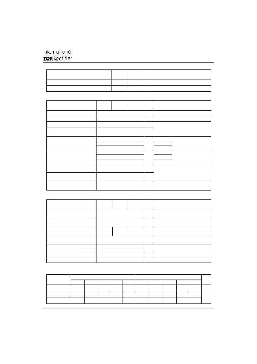
Thermal and Mechanical Specifications
T
J
Max. junction operating
-40 to 125
°C
temperature range
T
stg
Max. storage temperature
-40 to 150
°C
range
RthJC Max. thermal resistance,
0.18
0.16
K/W
DC operation, per junction
junction to case
RthCS Max. thermal resistance,
0.05
K/W
Mounting surface smooth, flat and greased
case to heatsink
Per module
T
Mounting
IAP to heatsink
4 to 6
Nm
torque ± 10% busbar to IAP
4 to 6
wt
Approximate weight
200 (7.1)
g(oz)
Case Style
New Int-A-Pak
A mounting compound is recommended and
the torque should be rechecked after a period
of 3 hours to allow for the spread of the
compound. Lubricated threads.
Triggering
P
GM
Max. peak gate power
12
W
tp
≤ 5ms, T
J = TJ max.
PG(AV) Max. average gate power
3
W
f=50Hz, T
J = TJ max.
I
GM
Max. peak gate current
3
A
tp
≤ 5ms, T
J = TJ max.
-V
GT
Max. peak negative
10
V
gate voltage
V
GT
Max. required DC gate
4
V
TJ = - 40°C
Anodesupply=6V,resistive
voltage to trigger
2.5
TJ = 25°C
load;Ra=1
1.7
TJ = TJmax.
I
GT
Max. required DC gate
270
TJ = - 40°C
Anodesupply=6V,resistive
current to trigger
150
mA
TJ = 25°C
load;Ra=1
80
TJ = TJmax.
V
GD
Max. gate voltage
0.3
V
@ T
J = TJ max., rated VDRMapplied
that will not trigger
I
GD
Max. gate current
10
mA
that will not trigger
di/
dt
Max. rate of rise of
300
A/s
@T
J=TJmax.,ITM=400Arated VDRMapplied
turned-on current
Sinusoidal conduction @ TJ max.
Rectangular conduction @ TJ max.
Devices
Units
180o
120o
90o
60o
30o
180o
120o
90o
60o
30o
IRK.136
0.007
0.01
0.013
0.0155
0.017
0.009
0.012
0.014
0.015
0.017
IRK.142
0.0019
0.0020
0.0021
0.0018
0.0022
0.0023
0.0020
K/W
IRK.162
0.0030
0.0031
0.0032
0.0033
0.0034
0.0029
0.0036
0.0039
0.0041
0.0040
R Conduction (per Junction)
(The following table shows the increment of thermal resistance R
thJC when devices operate at different conduction angles than DC)
Parameter
IRK.136
IRK.142
IRK.162
Units Conditions
Parameter
IRK.136
IRK.142
IRK.162
Units Conditions
Blocking
I
RRM
Maximum peak reverse and
50
mA
T
J = 125
o
C
IDRM off-state leakage current
V
INS
RMS isolation voltage
3500
V
50Hz, circuit to base, all terminals shorted, t = 1s
dV/dt critical rate of rise of off-state voltage
1000
V/s
TJ = TJ max., exponential to 67% rated VDRM
相关PDF资料 |
PDF描述 |
|---|---|
| IRKL162-12 | 355 A, 1200 V, SCR |
| IRKH162-14 | 355 A, 1400 V, SCR |
| IRKL162-14 | 355 A, 1400 V, SCR |
| IRKH142-16 | 310 A, 1600 V, SCR |
| IRKL142-16 | 310 A, 1600 V, SCR |
相关代理商/技术参数 |
参数描述 |
|---|---|
| IRKH162-14 | 制造商:IRF 制造商全称:International Rectifier 功能描述:THYRISTOR/DIODE and THYRISTOR/THYRISTOR |
| IRKH162-14D20 | 制造商:未知厂家 制造商全称:未知厂家 功能描述:THYRISTOR MODULE|DOUBLER|HALF-CNTLD|NEGATIVE|1.4KV V(RRM)|160A I(T) |
| IRKH162-14D20N | 制造商:未知厂家 制造商全称:未知厂家 功能描述:THYRISTOR MODULE|DOUBLER|HALF-CNTLD|POSITIVE|2KV V(RRM)|160A I(T) |
| IRKH162-16 | 制造商:IRF 制造商全称:International Rectifier 功能描述:THYRISTOR/DIODE and THYRISTOR/THYRISTOR |
| IRKH162-16D25 | 制造商:未知厂家 制造商全称:未知厂家 功能描述:THYRISTOR MODULE|DOUBLER|HALF-CNTLD|NEGATIVE|1.6KV V(RRM)|160A I(T) |
发布紧急采购,3分钟左右您将得到回复。