- 您现在的位置:买卖IC网 > PDF目录383144 > ISL6292-2CR4Z (INTERSIL CORP) Dual Positive-Edge-Triggered D-Type Flip-Flops With Clear and Preset 14-SOIC -40 to 85 PDF资料下载
参数资料
| 型号: | ISL6292-2CR4Z |
| 厂商: | INTERSIL CORP |
| 元件分类: | 电源管理 |
| 英文描述: | Dual Positive-Edge-Triggered D-Type Flip-Flops With Clear and Preset 14-SOIC -40 to 85 |
| 中文描述: | 1-CHANNEL POWER SUPPLY SUPPORT CKT, PQCC16 |
| 封装: | 4 X 4 MM, ROHS COMPLIANT, PLASTIC, MO-220VGGC, QFN-16 |
| 文件页数: | 15/19页 |
| 文件大小: | 647K |
| 代理商: | ISL6292-2CR4Z |
15
FN9105.6
July 25, 2005
When charging in the constant-current region, the pass
element in the charger is fully turned on. The charger is
equivalent to the on-resistance of the internal P-channel
MOSFET. The entire charging system is equivalent to the
circuit shown in Figure 25 (A). The charge current is the
constant current limit I
LIM
, and the adapter output voltage
can be easily found out as,
where V
PACK
is the battery pack voltage. The power
dissipation in the charger is given in EQ. 2, where I
CHARGE
= I
LIM
.
A critical condition of the adapter design is that the adapter
output reaches point B in Figure 24 at the same time as the
battery pack voltage reaches the final charge voltage (4.1V
or 4.2V), that is:
For example, if the final charge voltage is 4.2V, the r
DS(ON)
is 350m
, and the current limit I
LIM
is 750mA, the critical
adapter full-load voltage is 4.4625V.
When the above condition is true, the charger enters the
constant-voltage mode simultaneously as the adapter exits
the current-limit mode. The equivalent charging system is
shown in Figure 25 (C). Since the charge current drops at a
higher rate in the constant-voltage mode than the increase
rate of the adapter voltage, the power dissipation decreases
as the charge current decreases. Therefore, the worst case
thermal dissipation occurs in the constant-current charge
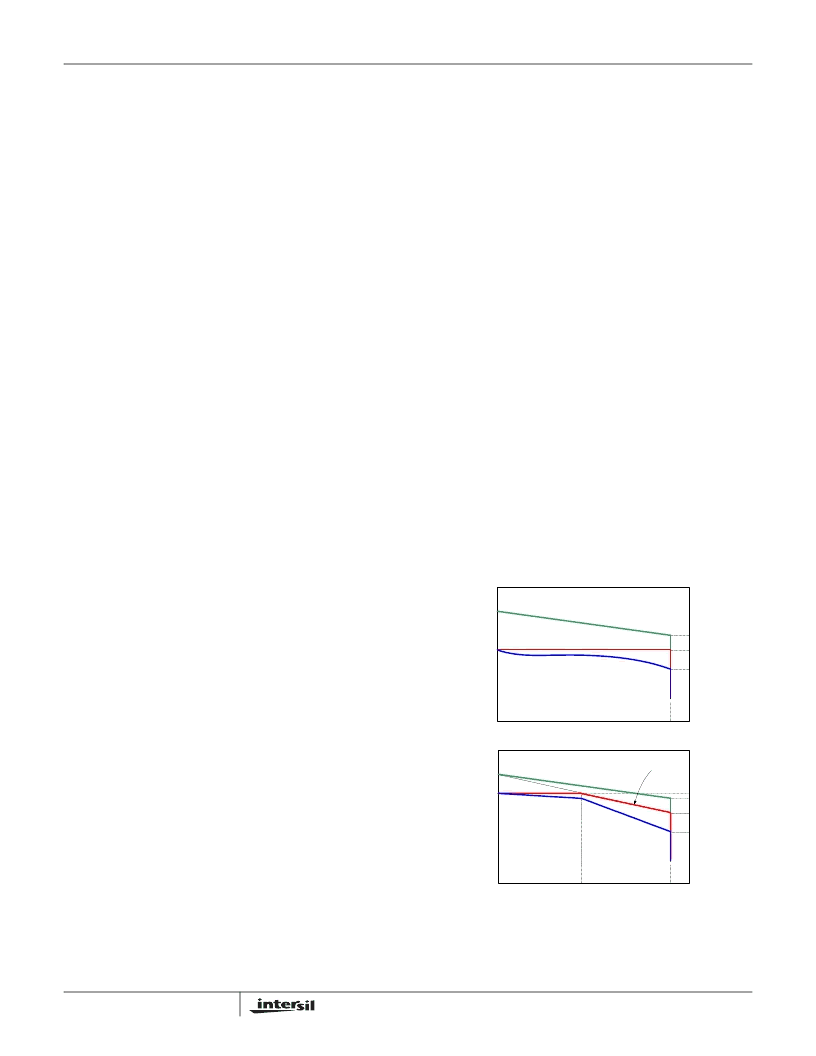
mode. Figure 26 (A) shows the I-V curves of the adapter
output, the battery pack voltage and the cell voltage during
the charge. The 5.9V no-load voltage is just an example
value higher than the full-load voltage. The cell voltage
4.05V uses the assumption that the pack resistance is
200m
. Figure 27 (A) illustrates the adapter voltage, battery
pack voltage, the charge current and the power dissipation in
the charger respectively in the time domain.
If the battery pack voltage reaches 4.2V (or 4.1V) before the
adapter reaches point B in Figure 24, a voltage step is
expected at the adapter output when the pack voltage
reaches the final charge voltage. As a result, the charger
power dissipation is also expected to have a step rise. This
case is shown in Figure 18 as well as Figure 27 (C). Under
this condition, the worst case thermal dissipation in the
charger happens when the charger enters the constant
voltage mode.
If the adapter voltage reaches the full-load voltage before the
pack voltage reaches 4.2V (or 4.1V), the charger will
experience the resistance-limit situation. In this situation, the
ON resistance of the charger is in series with the adapter output
resistance. The equivalent circuit for the resistance-limit region
is shown in Figure 25(B). Eventually, the battery pack voltage
will reach 4.2V (or 4.1V) because the adapter no-load voltage is
higher than 4.2V (or 4.1V), then Figure 25(C) becomes the
equivalent circuit until charging ends. In this case, the worst-
case thermal dissipation also occurs in the constant-current
charge mode. Figure 26 (B) shows the I-V curves of the
adapter output, the battery pack voltage and the cell voltage for
the case V
FL
= 4V. In the case, the full-load voltage is lower
than the final charge voltage (4.2V), but the charger is still able
to fully charge the battery as long as the no-load voltage is
above 4.2V. Figure 27 (B) illustrates the adapter voltage,
battery pack voltage, the charge current and the power
dissipation in the charger respectively in the time domain.
Based on the above discussion, the worst-case power
dissipation occurs during the constant-current charge mode
if the adapter full-load voltage is lower than the critical
voltage given in EQ. 14. Even if that is not true, the power
dissipation is still much less than the power dissipation in the
traditional linear charger. Figure 28 and 29 are scope-
captured waveforms to demonstrate the operation with a
current-limited adapter.
The waveforms in Figure 28 are the adapter output voltage
(1V/div), the battery voltage (1V/div), and the charge current
(200mA/div) respectively. The time scale is 1ks/div. The
adapter current is limited to 600mA and the charge current is
programmed to 1A. Note that the voltage difference is only
approximately 200mV and the adapter voltage tracks the
battery voltage in the CC mode. Figure 28 also shows the
resistance-limit mode before entering the CV mode.
V
Adapter
I
LIM
R
DS ON
)
V
PACK
+
=
(EQ. 13)
V
Critical
I
LIM
R
DS ON
)
V
CH
+
=
(EQ. 14)
FIGURE 26. THE I-V CHARACTERISTICS OF THE CHARGER
WITH DIFFERENT CURRENT LIMITED
ADAPTERS
(A)
(B)
0.75A
4.0V
3.775V
V
NL
0.55A
4.2V
3.625V
V
ADAPTER
V
CELL
V
PACK
4.2V
0.75A
4.4625V
4.2V
5.9V
4.2V
4.05V
V
ADAPTER
V
CELL
V
PACK
ISL6292
相关PDF资料 |
PDF描述 |
|---|---|
| ISL6292-2CR5 | Li-ion/Li Polymer Battery Charger |
| ISL6292-2CR5-T | Dual Positive-Edge-Triggered D-Type Flip-Flops With Clear and Preset 14-SSOP -40 to 85 |
| ISL6292-2CR5Z | Dual Positive-Edge-Triggered D-Type Flip-Flops With Clear and Preset 14-SSOP -40 to 85 |
| ISL6292 | Li-ion/Li Polymer Battery Charger |
| ISL6292-1CR3Z | Octal D-Type Edge-Triggered Flip-Flops with 3-State Outputs 20-PDIP -40 to 85 |
相关代理商/技术参数 |
参数描述 |
|---|---|
| ISL6292-2CR4Z-T | 功能描述:电池管理 LD VER OF ISL6292-2CR4-T RoHS:否 制造商:Texas Instruments 电池类型:Li-Ion 输出电压:5 V 输出电流:4.5 A 工作电源电压:3.9 V to 17 V 最大工作温度:+ 85 C 最小工作温度:- 40 C 封装 / 箱体:VQFN-24 封装:Reel |
| ISL6292-2CR5 | 功能描述:IC BATT CHRGR LI-ION 4.2V 16-QFN RoHS:否 类别:集成电路 (IC) >> PMIC - 电池管理 系列:- 标准包装:1 系列:- 功能:充电管理 电池化学:锂离子(Li-Ion)、锂聚合物(Li-Pol) 电源电压:3.75 V ~ 6 V 工作温度:-40°C ~ 85°C 安装类型:表面贴装 封装/外壳:SC-74A,SOT-753 供应商设备封装:SOT-23-5 包装:剪切带 (CT) 产品目录页面:669 (CN2011-ZH PDF) 其它名称:MCP73831T-2ACI/OTCT |
| ISL6292-2CR5-T | 功能描述:IC BATT CHRGR LI-ION 4.2V 16-QFN RoHS:否 类别:集成电路 (IC) >> PMIC - 电池管理 系列:- 标准包装:1 系列:- 功能:充电管理 电池化学:锂离子(Li-Ion)、锂聚合物(Li-Pol) 电源电压:3.75 V ~ 6 V 工作温度:-40°C ~ 85°C 安装类型:表面贴装 封装/外壳:SC-74A,SOT-753 供应商设备封装:SOT-23-5 包装:剪切带 (CT) 产品目录页面:669 (CN2011-ZH PDF) 其它名称:MCP73831T-2ACI/OTCT |
| ISL6292-2CR5Z | 功能描述:电池管理 LD VER OF ISL6292-2CR5 RoHS:否 制造商:Texas Instruments 电池类型:Li-Ion 输出电压:5 V 输出电流:4.5 A 工作电源电压:3.9 V to 17 V 最大工作温度:+ 85 C 最小工作温度:- 40 C 封装 / 箱体:VQFN-24 封装:Reel |
| ISL6292-2CR5Z-T | 功能描述:电池管理 LD VER OF ISL6292-2CR5-T RoHS:否 制造商:Texas Instruments 电池类型:Li-Ion 输出电压:5 V 输出电流:4.5 A 工作电源电压:3.9 V to 17 V 最大工作温度:+ 85 C 最小工作温度:- 40 C 封装 / 箱体:VQFN-24 封装:Reel |
发布紧急采购,3分钟左右您将得到回复。