- 您现在的位置:买卖IC网 > PDF目录30743 > LM1247AAG/NA/NOPB (NATIONAL SEMICONDUCTOR CORP) 3 CHANNEL, VIDEO PREAMPLIFIER, PDIP24 PDF资料下载
参数资料
| 型号: | LM1247AAG/NA/NOPB |
| 厂商: | NATIONAL SEMICONDUCTOR CORP |
| 元件分类: | 音频/视频放大 |
| 英文描述: | 3 CHANNEL, VIDEO PREAMPLIFIER, PDIP24 |
| 封装: | PLASTIC, DIP-24 |
| 文件页数: | 9/48页 |
| 文件大小: | 3141K |
| 代理商: | LM1247AAG/NA/NOPB |
第1页第2页第3页第4页第5页第6页第7页第8页当前第9页第10页第11页第12页第13页第14页第15页第16页第17页第18页第19页第20页第21页第22页第23页第24页第25页第26页第27页第28页第29页第30页第31页第32页第33页第34页第35页第36页第37页第38页第39页第40页第41页第42页第43页第44页第45页第46页第47页第48页
OSD Generator Operation (Continued)
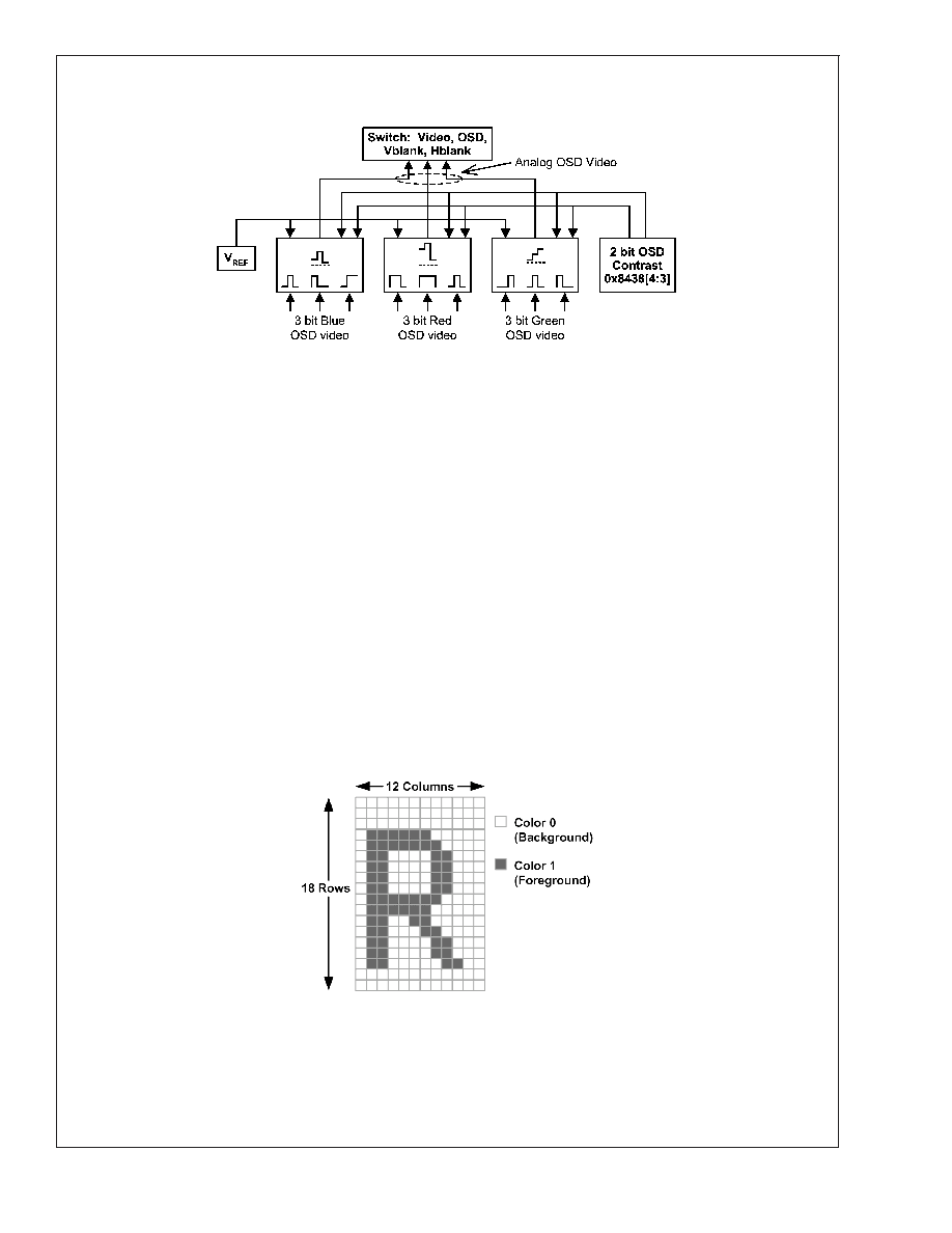
CHARACTER CELL
Each character is defined as a 12 column by 18 row matrix of
picture elements, or “pixels”. The character font is shown in
Figure 29 through Figure 36. There are two types of charac-
ters defined in the character ROM:
1.
Two-color: There are a total of 384 two-color characters
in 6 banks (banks 0, 1, 2, 4, 5 and 6). Each pixel of these
characters is defined by a single bit value. If the bit value
is 0, then the color is defined as “Color 0” or the “back-
ground” color. If the bit value is 1, then the color is
defined as “Color 1”, or the “foreground” color. An ex-
ample of a character is shown in Figure 15. The grid
lines are shown for clarity to delineate individual pixels
and are not part of the actual displayed character.
2.
Four-color: There are a total of 128 four-color charac-
ters, in two banks of 64 (banks 3 and 7). Each pixel of
the four-color character is defined by two bits of infor-
mation, and thus can define four different colors, Color
0, Color 1, Color 2 and Color 3. Color 0 is defined as the
“background” color. All other colors are considered “fore-
ground” colors, although for most purposes, any of the
four colors may be used in any way. Because each
four-color character has two bits, the LM1247 internally
has a matrix of two planes of ROM as shown in Figure
16. In that figure, dark pixels indicate a logic “1” and light
pixels which indicate a logic “0”. The left side shows
plane 0 which is the least significant bit and the middle
figure shows plane 1 which is the most significant bit.
The right side composite character formed when each
pixel is represented by its two bits formed from the two
planes. The color palette used in this example is “00” for
white, “01” for black, “10” for blue and “11” for red.
3.
By appropriately selecting the color attributes, it is pos-
sible to have two 2-color characters in one four color
ROM location. If the required number of four color char-
acters is less than 128, the remaining characters can be
used to increase the number of two color characters
from 384 to 384 + 2*N, where N is the number of unused
four color characters. This is explained in the next
section.
20048429
FIGURE 14. Block Diagram of OSD DACs
20048430
FIGURE 15. Two-Color Character
LM1247
www.national.com
17
相关PDF资料 |
PDF描述 |
|---|---|
| LM1253AAE/NA | ON-SCREEN DISPLAY IC, PDIP28 |
| LM1267NA/NOPB | 3 CHANNEL, VIDEO PREAMPLIFIER, PDIP24 |
| LM1269NA/NOPB | 3 CHANNEL, VIDEO PREAMPLIFIER, PDIP24 |
| LM1276AAA/NA | 1 CHANNEL, VIDEO PREAMPLIFIER, PDIP28 |
| LM1279AN/NOPB | 3 CHANNEL, VIDEO AMPLIFIER, PDIP20 |
相关代理商/技术参数 |
参数描述 |
|---|---|
| LM1247DMC/NA | 制造商:Texas Instruments 功能描述: |
| LM124A | 制造商:NSC 制造商全称:National Semiconductor 功能描述:Low Power Quad Operational Amplifiers |
| LM124AD | 制造商:STMICROELECTRONICS 制造商全称:STMicroelectronics 功能描述:LOW POWER QUAD OPERATIONAL AMPLIFIERS |
| LM124ADR | 制造商:TI 制造商全称:Texas Instruments 功能描述:QUADRUPLE OPERATIONAL AMPLIFIERS |
| LM124ADT | 制造商:未知厂家 制造商全称:未知厂家 功能描述:Voltage-Feedback Operational Amplifier |
发布紧急采购,3分钟左右您将得到回复。