- 您现在的位置:买卖IC网 > PDF目录98001 > LMZ1601-7R (POWER-ONE INC) 1-OUTPUT 50 W AC-DC REG PWR SUPPLY MODULE PDF资料下载
参数资料
| 型号: | LMZ1601-7R |
| 厂商: | POWER-ONE INC |
| 元件分类: | 电源模块 |
| 英文描述: | 1-OUTPUT 50 W AC-DC REG PWR SUPPLY MODULE |
| 文件页数: | 1/26页 |
| 文件大小: | 771K |
| 代理商: | LMZ1601-7R |
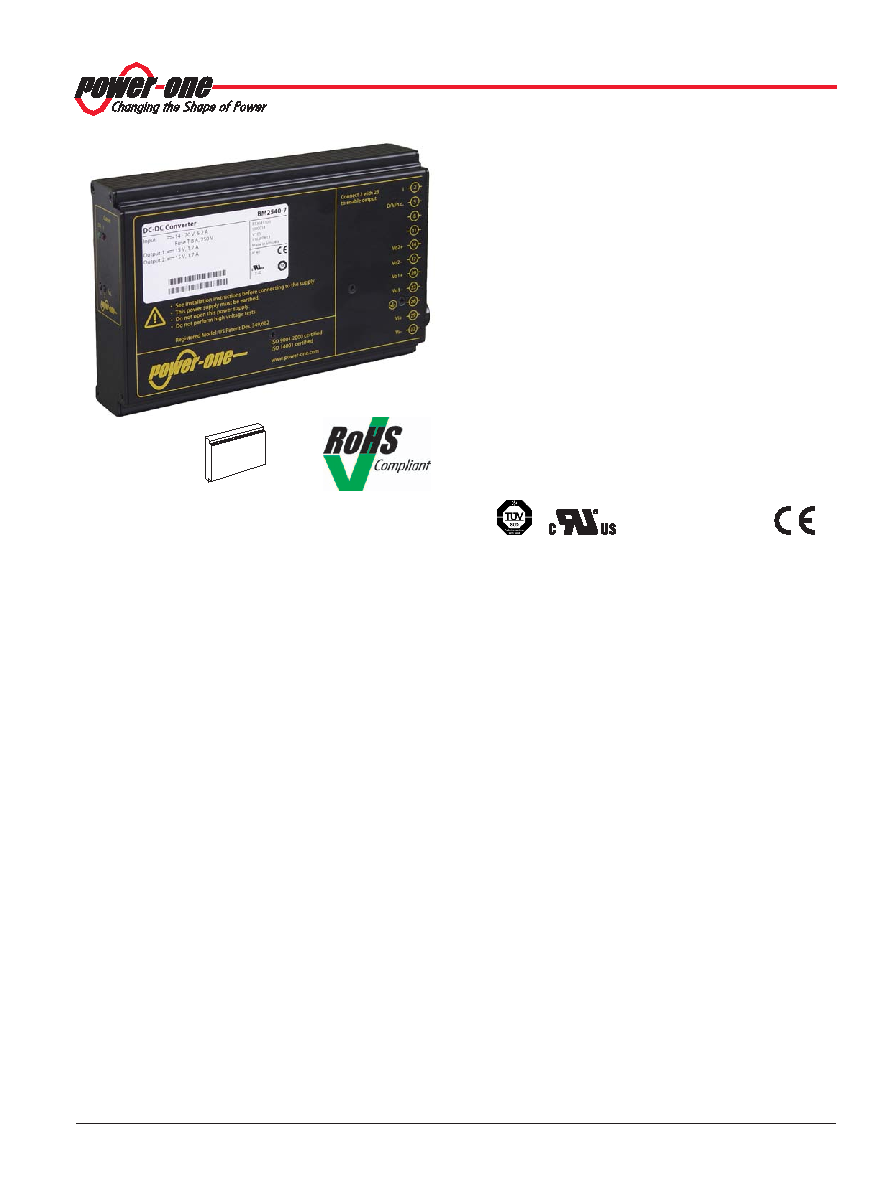
M Series Data Sheet
50 Watt DC-DC and AC-DC Converters
BCD20018 Rev AB
Page 1 of 26
www.power-one.com
Description
The M Series of DC-DC and AC-DC converters represents a
broad and flexible range of power supplies for use in advanced
industrial electronic systems. Features include high efficiency,
reliability, low output voltage noise and excellent dynamic
response to load/line changes due to individual regulation of
each output.
The converter inputs are protected against surges and
transients occuring at the source lines. An input over- and
undervoltage lockout circuit disables the outputs, if the input
voltage is outside the specified range. An inrush current
limitation prevents circuit breakers and fuses from tripping at
switch-on.
All outputs are open- and short-circuit proof, and are protected
against overvoltages by means of built-in suppressor diodes.
The outputs can be inhibited by a logic signal applied to the
connector (pin 2). If the inhibit function is not used, pin 2 should
be connected to pin 23 to enable the outputs.
LED indicators display the status of the converter and allow
visual monitoring of the system at any time.
Full input to output, input to case, output to case, and output to
output isolation is provided. The converters are designed and
built
according
to
the
international
safety
standard
IEC/EN 60950-1 and UL/CSA 60950-1, and they have been
approved by the safety agencies TV and UL.
The case design allows operation at nominal load up to 71 °C
in a free-air ambient temperature. If forced cooling is provided,
the ambient temperature may exceed 71 °C but the case
temperature should remain below 95 °C under all conditions.
A temperature sensor generates an inhibit signal, which
disables the outputs, when the case temperature TC exceeds
the limit. The outputs automatically recover, when the
temperature drops below the limit.
Various options are available to adapt the converters to
individual applications.
The converters may either be plugged into a 19" rack system
according to IEC 60927-3 or be mounted onto a chassis or a
plate.
Features
Extremly wide operating input voltage ranges from 8 to
385 VDC and 85 to 264 VAC, 47 to 440 Hz
RoHS lead-solder exemption compliant
Class I equipment
Input over- and undervoltage lockout
1, 2, or 3 individually isolated and controlled outputs up
to 64 V
Outputs: SELV, no load, overload, short-circuit proof,
rectangular current limiting characteristic
Adjustable output voltages with remote on/off
Immunity according to IEC/EN 61000-4-2, -3, -4, -5, -6
Emissions according to EN 55011/55022
PCBs protected by lacquer
Very high reliability
Battery charger models available
Table of Contents
Page
168
6.6"
39
1.54"
8TE
111
4.37"
3U
Safety according to IEC/EN 60950-1 and UL/CSA 60950-1
Description ............................................................................. 1
Model Selection ..................................................................... 2
Functional Description ........................................................... 4
Electrical Input Data ............................................................... 5
Electrical Output Data ............................................................ 7
Auxiliary Functions ............................................................... 10
Electromagnetic Compatibility (EMC) .................................. 13
Immunity to Environmental Conditions ................................ 15
Mechanical Data .................................................................. 16
Safety and Installation Instructions ...................................... 17
Description of Options ......................................................... 19
Accessories .......................................................................... 25
EC Declaration of Conformity .............................................. 26
相关PDF资料 |
PDF描述 |
|---|---|
| LNBP20CR | SPECIALTY ANALOG CIRCUIT, PZFM15 |
| LOG104AIDRE4 | LOG OR ANTILOG AMPLIFIER, 0.01 MHz BAND WIDTH, PDSO8 |
| LPR4150AL | SPECIALTY ANALOG CIRCUIT, PBGA28 |
| LPR430ALTR | SPECIALTY ANALOG CIRCUIT, PBGA28 |
| LPR430AL | SPECIALTY ANALOG CIRCUIT, PBGA28 |
相关代理商/技术参数 |
参数描述 |
|---|---|
| LMZ1901-7R | 制造商:POWER-ONE 制造商全称:Power-One 功能描述:50 Watt AC-DC Converters |
| LMZ20501EVM | 功能描述:LMZ20501 SIMPLE SWITCHER? DC/DC, Step Down 1, Non-Isolated Outputs Evaluation Board 制造商:texas instruments 系列:SIMPLE SWITCHER? 零件状态:有效 主要用途:DC/DC,步降 输出和类型:1,非隔离 功率 - 输出:- 电压 - 输出:1.8V 电流 - 输出:1A 电压 - 输入:2.7 V ~ 5.5 V 稳压器拓扑:降压 频率 - 开关:3MHz 板类型:完全填充 所含物品:板 使用的 IC/零件:LMZ20501 标准包装:1 |
| LMZ20501SILR | 功能描述:DC/DC CONVERTER 0.8-3.6V 4W 制造商:texas instruments 系列:SIMPLE SWITCHER? Nano 包装:剪切带(CT) 零件状态:有效 类型:非隔离 PoL 模块 输出数:1 电压 - 输入(最小值):2.7V 电压 - 输入(最大值):5.5V 电压 - 输出 1:0.8 ~ 3.6 V 电压 - 输出 2:- 电压 - 输出 3:- 电流 - 输出(最大值):1A 功率(W) - 制造系列:- 电压 - 隔离:- 应用:ITE(商业) 特性:远程开/关,OCP,OTP,SCP,UVLO 安装类型:表面贴装 封装/外壳:8-SMD 模块 大小/尺寸:0.14" 长 x 0.14" 宽 x 0.07" 高(3.5mm x 3.5mm x 1.8mm) 工作温度:-40°C ~ 125°C 效率:93% 功率(W) - 最大值:4W 标准包装:1 |
| LMZ20501SILT | 制造商:Texas Instruments 功能描述: |
| LMZ20502 | 制造商:TI 制造商全称:Texas Instruments 功能描述:LMZ20502 2A SIMPLE SWITCHER Nano Module |
发布紧急采购,3分钟左右您将得到回复。