- 您现在的位置:买卖IC网 > PDF目录365220 > M38748EAF-XXXFS (Mitsubishi Electric Corporation) SINGLE-CHIP 8-BIT CMOS MICROCOMPUTER PDF资料下载
参数资料
| 型号: | M38748EAF-XXXFS |
| 厂商: | Mitsubishi Electric Corporation |
| 英文描述: | SINGLE-CHIP 8-BIT CMOS MICROCOMPUTER |
| 中文描述: | 单芯片8位CMOS微机 |
| 文件页数: | 62/92页 |
| 文件大小: | 1292K |
| 代理商: | M38748EAF-XXXFS |
第1页第2页第3页第4页第5页第6页第7页第8页第9页第10页第11页第12页第13页第14页第15页第16页第17页第18页第19页第20页第21页第22页第23页第24页第25页第26页第27页第28页第29页第30页第31页第32页第33页第34页第35页第36页第37页第38页第39页第40页第41页第42页第43页第44页第45页第46页第47页第48页第49页第50页第51页第52页第53页第54页第55页第56页第57页第58页第59页第60页第61页当前第62页第63页第64页第65页第66页第67页第68页第69页第70页第71页第72页第73页第74页第75页第76页第77页第78页第79页第80页第81页第82页第83页第84页第85页第86页第87页第88页第89页第90页第91页第92页
62
3874 Group
SINGLE-CHIP 8-BIT CMOS MICROCOMPUTER
MITSUBISHI MICROCOMPUTERS
CLOCK GENERATING CIRCUIT
The 3874 group has two built-in oscillation circuits. An oscillation
circuit can be formed by connecting a resonator between X
IN
and
X
OUT
(X
CIN
and X
COUT
). Use the circuit constants in accordance
with the resonator manufacturer’s recommended values. No exter-
nal resistor is needed between X
IN
and X
OUT
since a feed-back
resistor exists on-chip. However, an external feed-back resistor is
needed between X
CIN
and X
COUT
.
Immediately after power on, only the X
IN
oscillation circuit starts
oscillating, and X
CIN
and X
COUT
pins function as I/O ports.
When using the X
CIN
oscillation circuit, X
CIN
and X
COUT
pins’ pull-
up resistors need to be invarid.
Frequency Control
(1) Middle-speed mode
The internal clock
φ
is the frequency of X
IN
divided by 8. After re-
set, this mode is selected.
(2) Double-speed mode
The internal clock
φ
is the frequency of X
IN
.
(3) High-speed mode
The internal clock
φ
is half the frequency of X
IN
.
(4) Low-speed mode
The internal clock
φ
is half the frequency of X
CIN
.
I
Note
When switching the mode between double/middle/high-speed and
low-speed, stabilize both X
IN
and X
CIN
oscillations. Sufficient time
is required for the sub clock to stabilize, especially immediately af-
ter power on and at returning from stop mode. When switching the
mode between double/middle/high-speed and low-speed, set the
frequency on condition that f(X
IN
) > 3f(X
CIN
).
It takes the cycle number mentioned below to switch between
each mode (machine cycle = cycle of internal clock
φ
).
Double-speed mode
→
Except double-speed mode
1 to 8 machine cycles
High-speed mode
→
Except high-speed mode
1 to 4 machine cycles
Middle-speed mode
→
Except middle-speed mode
1 machine cycle
Low-speed mode
→
Except low-speed mode
1 to 4 machine cycles
The 3874 group operates in the previous mode while the mode is
switched.
(5) Low power dissipation mode
The low power consumption operation can be realized by stopping
the main clock X
IN
in low-speed mode. To stop the main clock, set
bit 5 of the CPU mode register to “1”. When the main clock X
IN
is
restarted (by setting the main clock stop bit to “0”), set sufficient
time for oscillation to stabilize.
By clearing furthermore the X
COUT
drivability selection bit (b3) of
the CPU mode register to “0”, low power consumption operation
can be realized by reducing the drivability between X
CIN
and
X
COUT
. At reset or during STP instruction execution this bit is set
to “1” and a reduced drivability that has an easy oscillation start is
set. The sub-clock X
CIN
-X
COUT
oscillating circuit can no directly in-
put clocks that are generated externally. Accordingly, make sure to
cause an external resonator to oscillate.
Oscillation Control
(1) Stop mode
When the STP instruction is executed, the internal clock
φ
stops at
an “H” level, and X
IN
and X
CIN
oscillators stop. The value set to the
timer 1 latch and the timer 2 latch is set to timer 1 and timer 2. Ei-
ther X
IN
or X
CIN
divided by 16 is input to timer 1 as count source,
and the output of timer 1 is connected to timer 2. The bits of the
timer 123 mode register except the timer 3 count source selection
bit (b4) are cleared to “0”. Set the interrupt enable bits of timer 1
and timer 2 to the disabled state (“0”) before executing the STP in-
struction.
Oscillator restarts at reset or when an external interrupt is re-
ceived, but the internal clock
φ
is not supplied to the CPU until
timer 2 underflows. This allows time for the clock circuit oscillation
to stabilize. Timer 1 latch and timer 2 latch should be set to proper
values for stabilizing oscillation before executing the STP instruc-
tion.
(2) Wait mode
If the WIT instruction is executed, the internal clock
φ
stops at an
“H” level. The states of X
IN
and X
CIN
are the same as the state be-
fore executing the WIT instruction. The internal clock
φ
restarts at
reset or when an interrupt is received. Since the oscillator does
not stop, normal operation can be started immediately after the
clock is restarted.
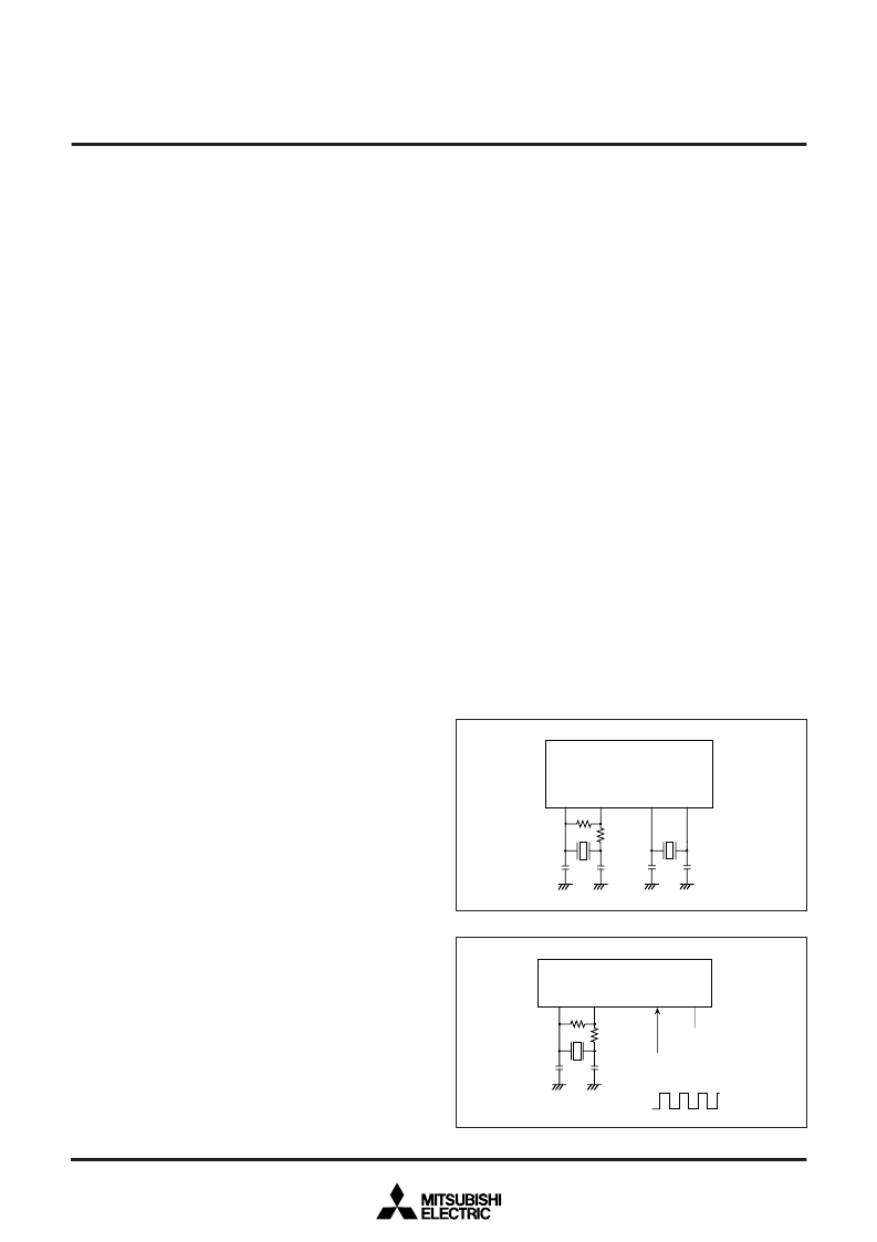
Fig. 68 Ceramic resonator circuit
Fig. 69 External clock input circuit
X
CIN
X
COUT
X
IN
X
OUT
C
IN
C
OUT
C
CIN
C
COUT
Rf
Rd
X
CIN
X
COUT
X
IN
X
OUT
Open
External oscillation
circuit
C
COUT
V
CC
V
SS
C
CIN
Rf
Rd
相关PDF资料 |
PDF描述 |
|---|---|
| M38748EAF-XXXGP | SINGLE-CHIP 8-BIT CMOS MICROCOMPUTER |
| M38748EDD-XXXFS | SINGLE-CHIP 8-BIT CMOS MICROCOMPUTER |
| M38748EDD-XXXGP | SINGLE-CHIP 8-BIT CMOS MICROCOMPUTER |
| M38748EDF-XXXFS | SINGLE-CHIP 8-BIT CMOS MICROCOMPUTER |
| M38748EDF-XXXGP | SINGLE-CHIP 8-BIT CMOS MICROCOMPUTER |
相关代理商/技术参数 |
参数描述 |
|---|---|
| M38748EAF-XXXGP | 制造商:MITSUBISHI 制造商全称:Mitsubishi Electric Semiconductor 功能描述:SINGLE-CHIP 8-BIT CMOS MICROCOMPUTER |
| M38748EAT-XXXFS | 制造商:MITSUBISHI 制造商全称:Mitsubishi Electric Semiconductor 功能描述:SINGLE-CHIP 8-BIT CMOS MICROCOMPUTER |
| M38748EAT-XXXGP | 制造商:MITSUBISHI 制造商全称:Mitsubishi Electric Semiconductor 功能描述:SINGLE-CHIP 8-BIT CMOS MICROCOMPUTER |
| M38748EBD-XXXFS | 制造商:MITSUBISHI 制造商全称:Mitsubishi Electric Semiconductor 功能描述:SINGLE-CHIP 8-BIT CMOS MICROCOMPUTER |
| M38748EBD-XXXGP | 制造商:MITSUBISHI 制造商全称:Mitsubishi Electric Semiconductor 功能描述:SINGLE-CHIP 8-BIT CMOS MICROCOMPUTER |
发布紧急采购,3分钟左右您将得到回复。