- 您现在的位置:买卖IC网 > PDF目录365220 > M38748EAF-XXXFS (Mitsubishi Electric Corporation) SINGLE-CHIP 8-BIT CMOS MICROCOMPUTER PDF资料下载
参数资料
| 型号: | M38748EAF-XXXFS |
| 厂商: | Mitsubishi Electric Corporation |
| 英文描述: | SINGLE-CHIP 8-BIT CMOS MICROCOMPUTER |
| 中文描述: | 单芯片8位CMOS微机 |
| 文件页数: | 66/92页 |
| 文件大小: | 1292K |
| 代理商: | M38748EAF-XXXFS |
第1页第2页第3页第4页第5页第6页第7页第8页第9页第10页第11页第12页第13页第14页第15页第16页第17页第18页第19页第20页第21页第22页第23页第24页第25页第26页第27页第28页第29页第30页第31页第32页第33页第34页第35页第36页第37页第38页第39页第40页第41页第42页第43页第44页第45页第46页第47页第48页第49页第50页第51页第52页第53页第54页第55页第56页第57页第58页第59页第60页第61页第62页第63页第64页第65页当前第66页第67页第68页第69页第70页第71页第72页第73页第74页第75页第76页第77页第78页第79页第80页第81页第82页第83页第84页第85页第86页第87页第88页第89页第90页第91页第92页
66
3874 Group
SINGLE-CHIP 8-BIT CMOS MICROCOMPUTER
MITSUBISHI MICROCOMPUTERS
Serial I/O3
When writing “1” to the serial I/O initialization bit of the serial
I/O3 control register 1, serial I/O3 is enabled, but each register
is not initialized. Set the value of each register by program.
A serial I/O3 interrupt request occurs when “0” is written to the
serial I/O initialization bit during an operation in automatic trans-
fer serial I/O mode. Disable the interrupt enable bit as necessary
by program.
A-D Converter/D-A Converter
The A-D/D-A conversion register functions as an A-D conversion
register during a read and a D-A conversion during a write. Ac-
cordingly, the D-A conversion register set value cannot be read
out.
The comparator for A-D converter uses capacitive coupling am-
plifier whose charge will be lost if the clock frequency is too low.
Therefore, make sure that f(X
IN
) is at least on 500 kHz during an
A-D conversion.
Do not execute the STP or WIT instruction during an A-D con-
version.
Instruction Execution Time
The instruction execution time is obtained by multiplying the fre-
quency of the internal clock
φ
by the number of cycles needed to
execute an instruction. The number of cycles required to execute
an instruction is shown in the list of machine instructions.
The frequency of the internal clock
φ
is half of the X
IN
frequency.
Data Link Layer Communication Control
The data link layer communication control circuit stops after a
reset. To restart or change modes, write “00XXXXX1
2
” to the
communication mode register. Note that bits 4 and 5 are read-
only bits.
The P7
5
/BUS
OUT
pin operates as a general-purpose pin after
release from reset. As a general-purpose port, its input/output
can be switched by the direction register.
Clock Changes
Use the LDM, STA, etc. instructions to modify the division ratio
of internal system clock
φ
. (Do not use read-modify-write instruc-
tions such as CLB, SEB, etc.)
Do not modify the division ratio of the internal system clock until
the mode has been changed. For details concerning the number
of cycles necessary to change modes, refer to the clock section
in the explanation of about function blocks.
Use the LDM, STA, etc., instructions to clear interrupt request
bits assigned to the interrupt source determination register 1,
the interrupt source determination register 2, the transmit status
register, or the receive status register. (Do not use read-modify-
write instructions such as CLB, SEB, etc.)
Before executing the CLI or RTI instruction during an interrupt
processing routine, use the LDM or STA instruction to clear the
interrupt request bits of interrupt source determination registers
which have completed the interrupt processing.
If switching the mode between low-speed and double-speed,
switch the mode to middle/high-speed first, and then switch the
mode to double-speed by program. Do not switch the mode
from low-speed to double-speed directly. 1 to 4 machine cycles
are required for switching from low-speed mode to other mode.
Insert “clock switch timing wait” for switching the mode to
middle/high-speed, and then switch the mode to double-speed.
Table 8 lists the recommended transition process for system
clock switch.
Figure 72 shows the program example.
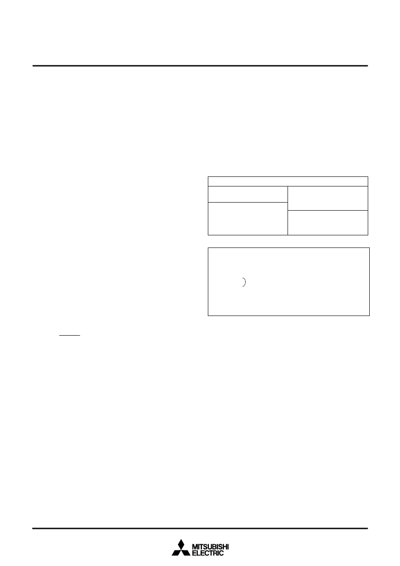
Table 8 Clock switch combination
Recommended transition process
Low-speed
→
High-speed
Low-speed
→
Middle-speed
Double-speed
→
High-speed
Double-speed
→
Middle-speed
Double-speed
→
Low-speed
Middle-speed
→
High-speed
Middle-speed
→
Middle-speed
Middle-speed
→
Low-speed
High-speed
→
Double-speed
High-speed
→
MIddle-speed
High-speed
→
Low-speed
Fig. 72 Program example
Low-speed mode
→
Middle/High-speed mode
→
Double-speed mode switch
LDM xx, CPUM Low-speed mode
→
Middle/High-speed mode switch
NOP
Clock switch timing wait
NOP
(1 to 4 machine cycles are required for switching mode.)
LDM yy, CPUM Switch mode to double-speed
Note:
CPUM = CPU mode register (address 003B
16
)
相关PDF资料 |
PDF描述 |
|---|---|
| M38748EAF-XXXGP | SINGLE-CHIP 8-BIT CMOS MICROCOMPUTER |
| M38748EDD-XXXFS | SINGLE-CHIP 8-BIT CMOS MICROCOMPUTER |
| M38748EDD-XXXGP | SINGLE-CHIP 8-BIT CMOS MICROCOMPUTER |
| M38748EDF-XXXFS | SINGLE-CHIP 8-BIT CMOS MICROCOMPUTER |
| M38748EDF-XXXGP | SINGLE-CHIP 8-BIT CMOS MICROCOMPUTER |
相关代理商/技术参数 |
参数描述 |
|---|---|
| M38748EAF-XXXGP | 制造商:MITSUBISHI 制造商全称:Mitsubishi Electric Semiconductor 功能描述:SINGLE-CHIP 8-BIT CMOS MICROCOMPUTER |
| M38748EAT-XXXFS | 制造商:MITSUBISHI 制造商全称:Mitsubishi Electric Semiconductor 功能描述:SINGLE-CHIP 8-BIT CMOS MICROCOMPUTER |
| M38748EAT-XXXGP | 制造商:MITSUBISHI 制造商全称:Mitsubishi Electric Semiconductor 功能描述:SINGLE-CHIP 8-BIT CMOS MICROCOMPUTER |
| M38748EBD-XXXFS | 制造商:MITSUBISHI 制造商全称:Mitsubishi Electric Semiconductor 功能描述:SINGLE-CHIP 8-BIT CMOS MICROCOMPUTER |
| M38748EBD-XXXGP | 制造商:MITSUBISHI 制造商全称:Mitsubishi Electric Semiconductor 功能描述:SINGLE-CHIP 8-BIT CMOS MICROCOMPUTER |
发布紧急采购,3分钟左右您将得到回复。