- 您现在的位置:买卖IC网 > PDF目录380322 > mA79M00KC (Texas Instruments, Inc.) NEGATIVE-VOLTAGE REGULATORS PDF资料下载
参数资料
| 型号: | mA79M00KC |
| 厂商: | Texas Instruments, Inc. |
| 英文描述: | NEGATIVE-VOLTAGE REGULATORS |
| 中文描述: | 负电压调节器 |
| 文件页数: | 3/11页 |
| 文件大小: | 188K |
| 代理商: | MA79M00KC |
μ
A79M00 SERIES
NEGATIVE-VOLTAGE REGULATORS
SLVS060E – JUNE 1976 – REVISED APRIL 2000
3
POST OFFICE BOX 655303
DALLAS, TEXAS 75265
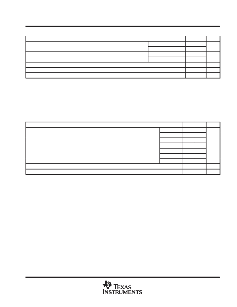
absolute maximum ratings over operating temperature range (unless otherwise noted)
μ
A79MxxC
UNIT
Input voltage
μ
A79M20C,
μ
A79M24C
All others
–40
V
–35
θ
JA(see Notes 1 and 2)
Package thermal impedance,
JA (see Notes 1 and 2)
KC package
22
°
C/W
KTP package
28
Operating free-air, TA; case, TC; or virtual junction, TJ, temperature range
Lead temperature 1,6 mm (1/16 inch) from case for 10 seconds
0 to 150
°
C
°
C
°
C
260
Storage temperature range, Tstg
Stresses beyond those listed under “absolute maximum ratings” may cause permanent damage to the device. These are stress ratings only, and
functional operation of the device at these or any other conditions beyond those indicated under “recommended operating conditions” is not
implied. Exposure to absolute-maximum-rated conditions for extended periods may affect device reliability.
NOTES:
1. Maximum power dissipation is a function of TJ(max),
θ
JA, and TA. The maximum allowable power dissipation at any allowable
ambient temperature is PD = (TJ(max) – TA)/
θ
JA. Operating at the absolute maximum TJ of 150
°
C can affect reliability. Due to
variations in individual device electrical characteristics and thermal resistance, the built-in thermal-overload protection may be
activated at power levels slightly above or below the rated dissipation.
2. The package thermal impedance is calculated in accordance with JESD 51.
–65 to 150
recommended operating conditions
MIN
–7
MAX
–25
UNIT
μ
A79M05C
μ
A79M06C
μ
A79M08C
μ
A79M12C
μ
A79M15C
μ
A79M20C
μ
A79M24C
–8
–25
–10.5
–25
Input voltage, VI
–14.5
30
V
–17.5
–30
–23
–35
–27
–38
Output current, IO
Operating virtual junction temperature, TJ
500
mA
°
C
0
125
相关PDF资料 |
PDF描述 |
|---|---|
| mA79M24Y | NEGATIVE-VOLTAGE REGULATORS |
| mA79M12CKTP | NEGATIVE-VOLTAGE REGULATORS |
| mA79M05CKTP | NEGATIVE-VOLTAGE REGULATORS |
| mA79M05Y | NEGATIVE-VOLTAGE REGULATORS |
| mA79M06Y | NEGATIVE-VOLTAGE REGULATORS |
相关代理商/技术参数 |
参数描述 |
|---|---|
| MA79M00KTP | 制造商:TI 制造商全称:Texas Instruments 功能描述:NEGATIVE-VOLTAGE REGULATORS |
| MA79M05CKC | 制造商:TI 制造商全称:Texas Instruments 功能描述:NEGATIVE-VOLTAGE REGULATORS |
| MA79M05CKTP | 制造商:TI 制造商全称:Texas Instruments 功能描述:NEGATIVE-VOLTAGE REGULATORS |
| MA79M05Y | 制造商:TI 制造商全称:Texas Instruments 功能描述:NEGATIVE-VOLTAGE REGULATORS |
| MA79M06CKTP | 制造商:TI 制造商全称:Texas Instruments 功能描述:NEGATIVE-VOLTAGE REGULATORS |
发布紧急采购,3分钟左右您将得到回复。