- 您现在的位置:买卖IC网 > PDF目录132985 > MTA85812S-10I/SS 8-BIT, OTPROM, 10 MHz, RISC MICROCONTROLLER, PDSO20 PDF资料下载
参数资料
| 型号: | MTA85812S-10I/SS |
| 元件分类: | 微控制器/微处理器 |
| 英文描述: | 8-BIT, OTPROM, 10 MHz, RISC MICROCONTROLLER, PDSO20 |
| 封装: | 0.209 INCH, PLASTIC, SSOP-20 |
| 文件页数: | 27/72页 |
| 文件大小: | 760K |
| 代理商: | MTA85812S-10I/SS |
第1页第2页第3页第4页第5页第6页第7页第8页第9页第10页第11页第12页第13页第14页第15页第16页第17页第18页第19页第20页第21页第22页第23页第24页第25页第26页当前第27页第28页第29页第30页第31页第32页第33页第34页第35页第36页第37页第38页第39页第40页第41页第42页第43页第44页第45页第46页第47页第48页第49页第50页第51页第52页第53页第54页第55页第56页第57页第58页第59页第60页第61页第62页第63页第64页第65页第66页第67页第68页第69页第70页第71页第72页
1995 Microchip Technology Inc.
DS40115C-page 33
MTA85XXX
15.2
DC Characteristics
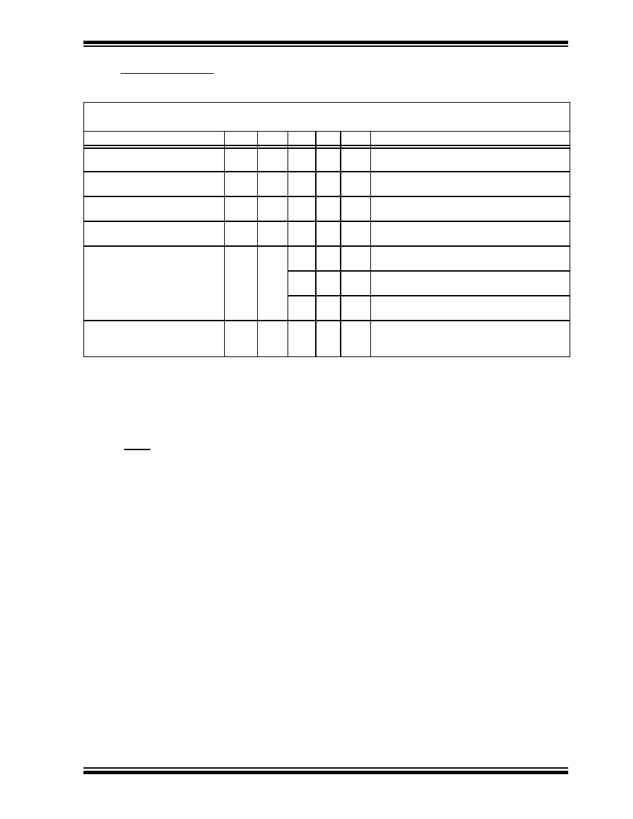
TABLE 15-2:
DC CHARACTERISTICS OF MICROCONTROLLER MTA854XX-04 (INDUSTRIAL)
DC CHARACTERISTICS
Power Supply Pins
Standard Operating Conditions
Operating temperature
-40
°C ≤ TA ≤ +85°C for industrial
Characteristic
Sym
Min
Typ* Max Units
Conditions
Supply Voltage
VDD
3.0
4.5
6.25
5.5
V
XT, RC and LP options
HS option
RAM Data Retention
Voltage (Note 3)
VDR
1.5
V
Device in SLEEP mode
VDD start voltage to
guarantee Power-On Reset
VPOR
VSS
V
See POR section in microcontroller datasheet
for details on Power-On Reset
VDD rise rate to guarantee
Power-On Reset
SVDD
0.05*
V/ms See POR section in microcontroller datasheet
for details on Power-On Reset
Supply Current (Note 2)
IDD
1.8
2.4
mA
XT and RC options (C-04)
FOSC = 4 MHz, VDD = 5.5V
5.8
13
mA
HS option (C-10)
FOSC = 10 MHz, VDD = 5.5V
17
70
A
LP option, Industrial, EEPROM standby
FOSC = 32 kHz, VDD = 3.0V, WDT disabled
Power Down Current (Note 4)
WDT enabled
WDT disabled
IPD
5
13
14
5
A
VDD = 3.0V, Industrial
*
These parameters are characterized but not tested.
Note 1: Data in the column labeled "Typ" is based on characterization results at 25
°C. These parameters are for
design guidance only and are not tested for, or guaranteed by Microchip Technology.
Note 2: The supply current is mainly a function of the operating voltage and frequency. Other factors such as bus
loading, oscillator type, bus rate, internal code execution pattern, and temperature also have an impact on
the current consumption.
a) The test conditions for all IDD measurements in active operation mode are:
OSC1= external square wave, from rail to rail; all I/O pins tristated, pulled to VDD, RT = VDD,
MCLR = VDD; WDT enabled/disabled as specified; EEPROM in write condition (except LP mode).
b) For standby current measurements, the conditions are the same, except that the device is in SLEEP
mode and SDA and SCL are tied to VSS.
Note 3: This is the limit to which VDD can be lowered in SLEEP mode without losing RAM data.
Note 4: The power down current in SLEEP mode does not depend on the oscillator type. Power down current is
measured with the part in SLEEP mode, with all I/O pins in hi-impedance state and tied to VDD and VSS;
SDA and SCL tied to VSS.
Note 5: Does not include current through Rext. The current through the resistor can be estimated by the formula
Ir = VDD/2Rext (mA) with Rext in k
.
相关PDF资料 |
PDF描述 |
|---|---|
| MB91661PMC | 32-BIT, MROM, 33 MHz, RISC MICROCONTROLLER, PQFP120 |
| MPC8266ACZULHDX | 32-BIT, 250 MHz, RISC PROCESSOR, PBGA480 |
| MPC8266ACZUPIBX | 32-BIT, 300 MHz, RISC PROCESSOR, PBGA480 |
| MPC8266AZULHDX | 32-BIT, 250 MHz, RISC PROCESSOR, PBGA480 |
| MPC8266AZUPIBX | 32-BIT, 300 MHz, RISC PROCESSOR, PBGA480 |
相关代理商/技术参数 |
参数描述 |
|---|---|
| MTA8808 | 制造商:Pulse Electronics Corporation 功能描述: |
| MTA8ATF1G64AZ-2G3B1 | 功能描述:Memory Module DDR4 SDRAM 8GB 2400MT/s 288-UDIMM 制造商:micron technology inc. 系列:- 零件状态:在售 存储器类型:DDR4 SDRAM 存储容量:8GB 速度:2400MT/s 封装/外壳:288-UDIMM 标准包装:1 |
| MTA8ATF1G64HZ-2G3B1 | 功能描述:Memory Module DDR4 SDRAM 8GB 2400MT/s 260-SODIMM 制造商:micron technology inc. 系列:- 零件状态:在售 存储器类型:DDR4 SDRAM 存储容量:8GB 速度:2400MT/s 封装/外壳:260-SODIMM 标准包装:1 |
| MTA8D50 | 制造商:Mallory Sonalert Products Inc 功能描述:Molded Tubular Aluminum Electrolytic Axial Leads Capacitor - 8uF 50dcV -10+100% |
| MTA90A | 制造商:LIUJING 制造商全称:LIUJING 功能描述:可控硅(晶闸管) |
发布紧急采购,3分钟左右您将得到回复。