参数资料
| 型号: | ISL6336ACRZ |
| 厂商: | Intersil |
| 文件页数: | 12/31页 |
| 文件大小: | 0K |
| 描述: | IC CTRLR PWM 6PHASE BUCK 48-QFN |
| 标准包装: | 43 |
| 应用: | 控制器,Intel VR11.1 |
| 输入电压: | 3 V ~ 12 V |
| 输出数: | 1 |
| 输出电压: | 0.5 V ~ 1.6 V |
| 工作温度: | 0°C ~ 70°C |
| 安装类型: | 表面贴装 |
| 封装/外壳: | 48-VFQFN 裸露焊盘 |
| 供应商设备封装: | 48-QFN(7x7) |
| 包装: | 管件 |
第1页第2页第3页第4页第5页第6页第7页第8页第9页第10页第11页当前第12页第13页第14页第15页第16页第17页第18页第19页第20页第21页第22页第23页第24页第25页第26页第27页第28页第29页第30页第31页
�� �
�
�ISL6336,� ISL6336A�
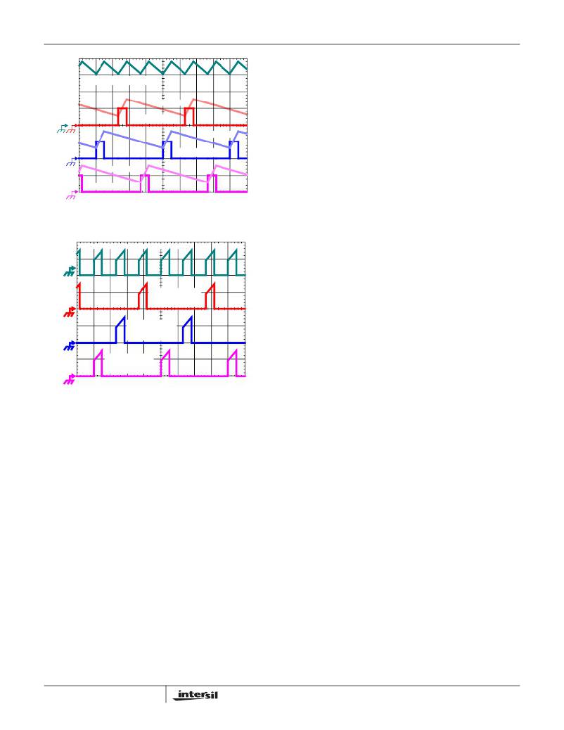
�The� converter� depicted� in� Figure� 2� delivers� 36A� to� a� 1.5V� load�
�from� a� 12V� input.� The� RMS� input� capacitor� current� is� 5.9A.�
�IL1 + IL2 + IL3, 7A/DIV�
�I� L3, 7A/DI� V�
�PWM3, 5V/DIV�
�I� L2, 7A/DIV�
�Compare� this� to� a� single-phase� converter� also� stepping� down�
�12V� to� 1.5V� at� 36A.� The� single-phase� converter� has� 11.9A� RMS�
�input� capacitor� current.� The� single-phase� converter� must� use�
�an� input� capacitor� bank� with� twice� the� RMS� current� capacity� as�
�the� equivalent� three-phase� converter.�
�Figures� 21,� 22� and� 23� in� the� section� entitled� “Input� Capacitor�
�I� C� ,� PP� =� -------------------------------------------------------------------------�
�L� ?� f� S� ?� V�
�PWM2, 5V/DIV�
�I� L1, 7A/DIV�
�P� WM1, 5V/DI� V�
�1μs/DIV�
�FIGURE� 1.� PWM� AND� INDUCTOR-CURRENT� WAVEFORMS�
�FOR� 3-PHASE� CONVERTER�
�INPUT-CAPACITOR� CURRENT�
�CHANNEL� 3�
�INPUT�
�CHANNEL� 2�
�INPUT�
�CHANNEL� 1�
�INPUT�
�1μs/DIV�
�FIGURE� 2.� CHANNEL� INPUT� CURRENTS� AND� INPUT�
�CAPACITOR� RMS� CURRENT� FOR� 3-PHASE�
�CONVERTER�
�The� output� capacitors� conduct� the� ripple� component� of� the�
�inductor� current.� In� the� case� of� multiphase� converters,� the�
�capacitor� current� is� the� sum� of� the� ripple� currents� from� each� of�
�the� individual� channels.� Compare� Equation� 1� to� the� expression�
�for� the� peak-to-peak� current� after� the� summation� of� N�
�symmetrically� phase-shifted� inductor� currents� in� Equation� 2.�
�Peak-to-peak� ripple� current� decreases� by� an� amount�
�proportional� to� the� number� of� channels.� Output-voltage� ripple� is�
�a� function� of� capacitance,� capacitor� equivalent� series�
�resistance� (ESR),� and� inductor� ripple� current.� Reducing� the�
�inductor� ripple� current� allows� the� designer� to� use� fewer� or� less�
�costly� output� capacitors.�
�(� V� IN� –� (� N� ?� V� OUT� )� )� ?� V� OUT�
�(EQ.� 2)�
�IN�
�Another� benefit� of� interleaving� is� to� reduce� the� input� ripple�
�current.� The� input� capacitance� is� determined� in� part� by� the�
�maximum� input� ripple� current.� Multiphase� topologies� can�
�improve� the� overall� system� cost� and� size� by� lowering� the�
�input� ripple� current� and� allowing� the� designer� to� reduce� the�
�cost� of� input� capacitance.� The� example� in� Figure� 2� illustrates�
�the� input� currents� from� a� three-phase� converter� combining� to�
�reduce� the� total� input� ripple� current.�
�12�
�Selection”� on� page� 29� can� be� used� to� determine� the� input�
�capacitor� RMS� current� based� on� the� load� current,� the� duty�
�cycle,� and� the� number� of� channels.� They� are� provided� as�
�aids� in� determining� the� optimal� input� capacitor� solution.�
�Figure� 24� shows� the� single� phase� input-capacitor� RMS�
�current� for� comparison.�
�PWM� Modulation� Scheme�
�The� ISL6336,� ISL6336A� adopts� Intersil's� proprietary� Active�
�Pulse� Positioning� (APP)� modulation� scheme� to� improve� the�
�transient� performance.� APP� control� is� a� unique� dual-edge�
�PWM� modulation� scheme� with� both� PWM� leading� and�
�trailing� edges� being� independently� moved� to� provide� the�
�best� response� to� the� transient� loads.� The� PWM� frequency,�
�however,� is� constant� and� set� by� the� external� resistor�
�between� the� FS� pin� and� GND.�
�To� further� improve� the� transient� response,� the� ISL6336,�
�ISL6336A� also� implements� Intersil's� proprietary� Adaptive�
�Phase� Alignment� (APA)� technique.� The� APA,� with� sufficiently�
�large� load� step� currents,� can� turn� on� all� phases� simultaneously.�
�With� both� APP� and� APA� control,� ISL6336,� ISL6336A� can�
�achieve� excellent� transient� performance� and� reduce� the�
�demand� on� the� output� capacitors.�
�Under� steady� state� conditions� the� operation� of� the� ISL6336,�
�ISL6336A� PWM� modulator� appears� to� be� that� of� a� conventional�
�trailing� edge� modulator.� Conventional� analysis� and� design�
�methods� can� therefore� be� used� for� steady� state� and� small�
�signal� operation.�
�PWM� and� PSI#� Operation�
�The� timing� of� each� converter� is� set� by� the� number� of� active�
�channels.� The� default� channel� setting� for� the� ISL6336,�
�ISL6336A� is� six.� The� switching� cycle� is� defined� as� the� time�
�between� PWM� pulse� termination� signals� of� each� channel.�
�The� cycle� time� of� the� pulse� termination� signal� is� the� inverse�
�of� the� switching� frequency� set� by� the� resistor� between� the�
�FS� pin� and� ground.� The� PWM� signals� command� the�
�MOSFET� drivers� to� turn� on/off� the� channel� MOSFETs.�
�In� the� default� 6-phase� operation,� the� PWM2� pulse� happens�
�1/6� of� a� cycle� after� PWM1,� the� PWM3� pulse� happens� 1/6� of�
�a� cycle� after� PWM2,� etc.�
�The� ISL6336,� ISL6336A� works� in� a� 1-� to� 6-phase� configuration.�
�Connecting� the� PWM6� pin� to� VCC� selects� 5-phase� operation�
�and� the� pulse� times� are� spaced� in� 1/5� cycle� increments.�
�FN6504.1�
�May� 28,� 2009�
�相关PDF资料 |
PDF描述 |
|---|---|
| RSA24DRMH | CONN EDGECARD 48POS .125 SQ WW |
| 2512-182K | POWER INDUCTOR 1.8UH SMD |
| X40021S14-BT1 | IC VOLTAGE MONITOR DUAL 14-SOIC |
| HSC08DTES | CONN EDGECARD 16POS .100 EYELET |
| ISL6265CHRTZ-T | IC CTRLR MULTI-OUTPUT 48TQFN |
相关代理商/技术参数 |
参数描述 |
|---|---|
| P89LPC9351FDH | 制造商:PHILIPS 制造商全称:NXP Semiconductors 功能描述:8-bit microcontroller with accelerated two-clock 80C51 core 8 kB 3 V byte-erasable flash with 8-bit ADC |
| P89LPC9351FDH,518 | 功能描述:8位微控制器 -MCU Enhanced LPC935 RoHS:否 制造商:Silicon Labs 核心:8051 处理器系列:C8051F39x 数据总线宽度:8 bit 最大时钟频率:50 MHz 程序存储器大小:16 KB 数据 RAM 大小:1 KB 片上 ADC:Yes 工作电源电压:1.8 V to 3.6 V 工作温度范围:- 40 C to + 105 C 封装 / 箱体:QFN-20 安装风格:SMD/SMT |
| P89LPC935FA | 制造商:NXP Semiconductors 功能描述:IC MCU 8BIT 80C51 8K FLASH PLCC28 |
| P89LPC935FA,129 | 功能描述:8位微控制器 -MCU 80C51 8K FL 768B RAM RoHS:否 制造商:Silicon Labs 核心:8051 处理器系列:C8051F39x 数据总线宽度:8 bit 最大时钟频率:50 MHz 程序存储器大小:16 KB 数据 RAM 大小:1 KB 片上 ADC:Yes 工作电源电压:1.8 V to 3.6 V 工作温度范围:- 40 C to + 105 C 封装 / 箱体:QFN-20 安装风格:SMD/SMT |
| P89LPC935FA129 | 制造商:NXP Semiconductors 功能描述:IC 8BIT MCU 80C51 18MHZ LCC-28 |
发布紧急采购,3分钟左右您将得到回复。