- 您现在的位置:买卖IC网 > PDF目录69322 > RH80530WZ014256 (INTEL CORP) 32-BIT, 1333 MHz, MICROPROCESSOR, CPGA478 PDF资料下载
参数资料
| 型号: | RH80530WZ014256 |
| 厂商: | INTEL CORP |
| 元件分类: | 微控制器/微处理器 |
| 英文描述: | 32-BIT, 1333 MHz, MICROPROCESSOR, CPGA478 |
| 封装: | MICRO, FLIP CHIP, PGA-478 |
| 文件页数: | 15/91页 |
| 文件大小: | 1142K |
| 代理商: | RH80530WZ014256 |
第1页第2页第3页第4页第5页第6页第7页第8页第9页第10页第11页第12页第13页第14页当前第15页第16页第17页第18页第19页第20页第21页第22页第23页第24页第25页第26页第27页第28页第29页第30页第31页第32页第33页第34页第35页第36页第37页第38页第39页第40页第41页第42页第43页第44页第45页第46页第47页第48页第49页第50页第51页第52页第53页第54页第55页第56页第57页第58页第59页第60页第61页第62页第63页第64页第65页第66页第67页第68页第69页第70页第71页第72页第73页第74页第75页第76页第77页第78页第79页第80页第81页第82页第83页第84页第85页第86页第87页第88页第89页第90页第91页
22
Datasheet
Electrical Specifications
NOTES:
1. Unless otherwise noted, all specifications in this table are based on latest post-silicon measurements
available at the time of publication.
2. These voltages are targets only. A variable voltage source should exist on systems in the event that a
different voltage is required. See Section 2.4 and Table 3 for more information. The VID bits will set the
typical VCC with the minimum being defined according to current consumption at that voltage.
3. The voltage specification requirements are measured at the system board socket ball with a 100-MHz
bandwidth oscilloscope, 1.5-pF maximum probe capacitance, and 1-M
minimum impedance. The maximum
length of ground wire on the probe should be less than 5 mm. Ensure external noise from the system is not
coupled in the scope probe.
4. Refer to Table 8 to Table 9 and Figure 4 to Figure 5 for the minimum, typical, and maximum VCC (measured
at the system board socket ball) allowed for a given current. The processor should not be subjected to any
VCC and ICC combination wherein VCC exceeds VCC_MAX for a given current. Failure to adhere to this
specification can affect the long term reliability of the processor.
5. VCC_MIN is defined at ICC_MAX.
6. The current specified is also for AutoHALT state.
7. Typical VCC indicates the VID encoded voltage. Voltage supplied must conform to the load line specification
8. The maximum instantaneous current the processor will draw while the thermal control circuit is active as
indicated by the assertion of PROCHOT# is the same as the maximum ICC for the processor.
9. Maximum specifications for ICC Core, ICC Stop-Grant, ICC Sleep, and ICC Deep Sleep are specified at VCC
static Max. derived from the tolerances in Table 8 through Table 9. TJ Max., and under maximum signal
loading conditions.
10.The specification is defined per PLL pin.
11.The voltage response to a processor current load step (transient) must stay within the transient voltage
tolerance window. The voltage surge or droop response measured in this window is typically on the order of
several hundred nanoseconds to several microseconds. The Transient Voltage Tolerance Window is defined
as follows:
Case a) Load Current Step Up: e.g., from Icc = I_leakage to Icc = Icc_max. Allowable Vcc_min is defined as
minimum transient voltage at Icc = Icc_max for a period of time lasting several hundred nanoseconds to
several microseconds after the transient event.
Case b) Load Current Step Down: e.g., form Icc = Icc_max to Icc = I_leakage. Allowable Vcc_max is defined
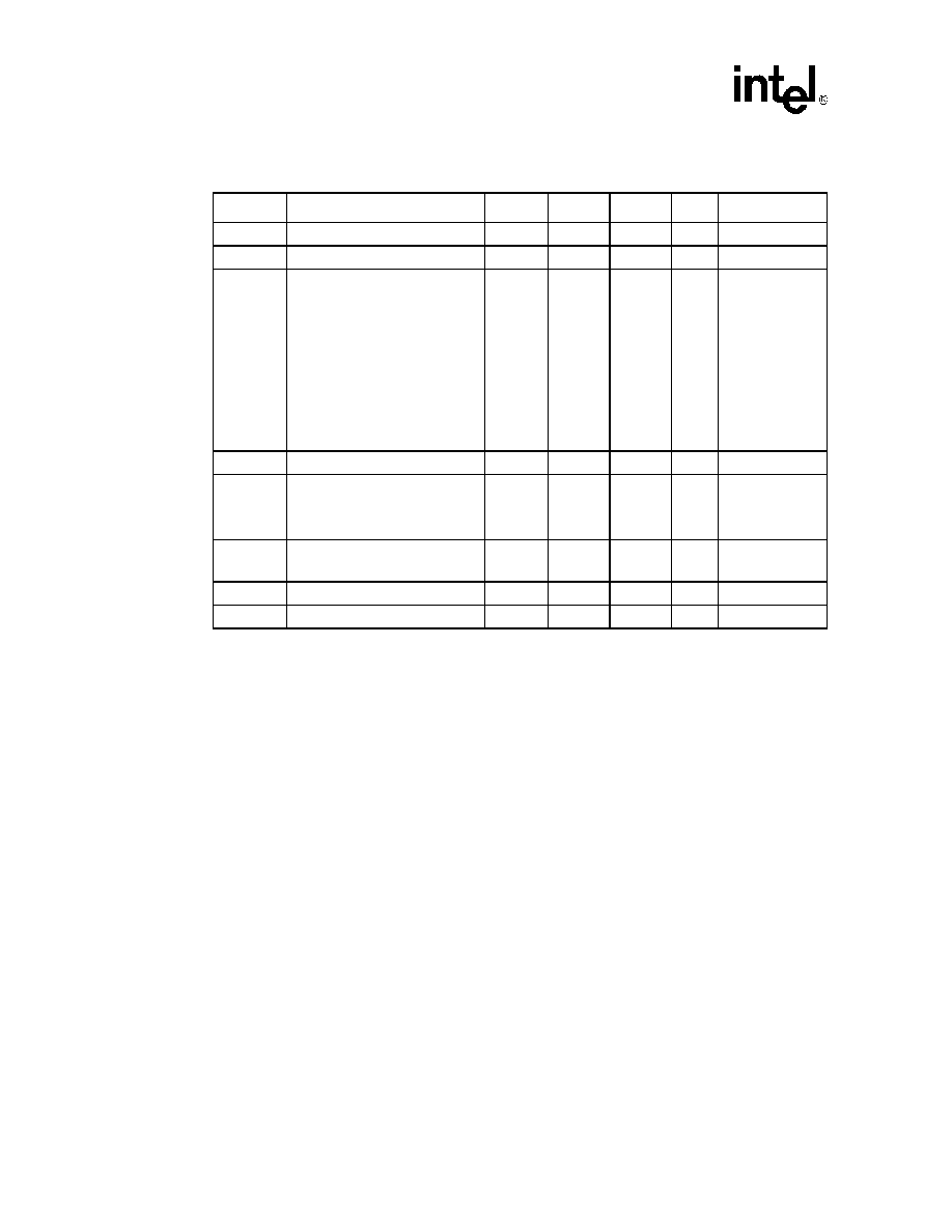
Table 7.
Voltage and Current Specifications
Symbol
Parameter
Min
Typ
Max
Unit
Notes1
VCC
VCC for core logic
1.30
V
2, 3, 4, 5, 7, 8,11
VCCVID
VID supply voltage
-5%
1.20
+10%
V
2, 12
ICC
Current for VCC at core frequency
2.50 GHz & 1.30 V
2.40 GHz & 1.30 V
2.20 GHz & 1.30 V
2.00 GHz & 1.30 V
1.80 GHz & 1.30 V
1.70 GHz & 1.30 V
1.60 GHz & 1.30 V
1.50 GHz & 1.30 V
1.40 GHz & 1.30 V
1.20 GHz & 1.30 V13
37.7
36.7
34.5
33.3
31.0
29.9
28.7
27.5
26.3
23.0
A
4, 5, 8, 9
IVCCVID
Current for VID supply
300
mA
ISGNT, ISLP
ICC Stop-Grant and ICCSleep at
1.30 V (for > 2.0 GHz)
1.30 V (for <= 2.0 GHz)
10.5
10.1
A
6, 9
IDSLP
ICC Deep Sleep at
1.30 V
9.0
A
9
ITCC
ICC TCC active
ICC
A8
ICC PLL
ICC for PLL pins
60
mA
10
相关PDF资料 |
PDF描述 |
|---|---|
| RH80532NC021256 | 32-BIT, 1500 MHz, MICROPROCESSOR, CPGA478 |
| RH80532GC025512 | 32-BIT, 1600 MHz, MICROPROCESSOR, CPGA478 |
| RH80532GC021512 | 32-BIT, 1500 MHz, MICROPROCESSOR, CPGA478 |
| RH80532GC017512 | 32-BIT, 1400 MHz, MICROPROCESSOR, CPGA478 |
| RH80536GE0362M | 1860 MHz, MICROPROCESSOR, CPGA478 |
相关代理商/技术参数 |
参数描述 |
|---|---|
| RH80532GC029512 | 制造商:未知厂家 制造商全称:未知厂家 功能描述:Microprocessor |
| RH80532GC029512S L6FG | 功能描述:IC PENTIUM 4 1.7GHZ UFC-PGA RoHS:否 类别:集成电路 (IC) >> 嵌入式 - 微处理器 系列:- 标准包装:60 系列:SCC 处理器类型:Z380 特点:全静电 Z380 CPU 速度:20MHz 电压:5V 安装类型:表面贴装 封装/外壳:144-LQFP 供应商设备封装:144-LQFP 包装:托盘 |
| RH80532GC029512S L6V6 | 制造商:Intel 功能描述:MPU Pentium? 4 Processor-M 0.13um 1.7GHz 478-Pin uFCPGA |
| RH80532GC029512SL6V6 | 制造商:Intel 功能描述:MPU Pentium 4 Processor-M 0.13um 1.7GHz 478-Pin uFCPGA |
| RH80532GC033512 | 制造商:未知厂家 制造商全称:未知厂家 功能描述:Microprocessor |
发布紧急采购,3分钟左右您将得到回复。