- 您现在的位置:买卖IC网 > PDF目录69378 > ST7PL38F2MC/XXXE (STMICROELECTRONICS) 8-BIT, MROM, 8 MHz, MICROCONTROLLER, PDSO20 PDF资料下载
参数资料
| 型号: | ST7PL38F2MC/XXXE |
| 厂商: | STMICROELECTRONICS |
| 元件分类: | 微控制器/微处理器 |
| 英文描述: | 8-BIT, MROM, 8 MHz, MICROCONTROLLER, PDSO20 |
| 封装: | 0.300 INCH, ROHS COMPLIANT, PLASTIC, SOP-20 |
| 文件页数: | 105/168页 |
| 文件大小: | 2955K |
| 代理商: | ST7PL38F2MC/XXXE |
第1页第2页第3页第4页第5页第6页第7页第8页第9页第10页第11页第12页第13页第14页第15页第16页第17页第18页第19页第20页第21页第22页第23页第24页第25页第26页第27页第28页第29页第30页第31页第32页第33页第34页第35页第36页第37页第38页第39页第40页第41页第42页第43页第44页第45页第46页第47页第48页第49页第50页第51页第52页第53页第54页第55页第56页第57页第58页第59页第60页第61页第62页第63页第64页第65页第66页第67页第68页第69页第70页第71页第72页第73页第74页第75页第76页第77页第78页第79页第80页第81页第82页第83页第84页第85页第86页第87页第88页第89页第90页第91页第92页第93页第94页第95页第96页第97页第98页第99页第100页第101页第102页第103页第104页当前第105页第106页第107页第108页第109页第110页第111页第112页第113页第114页第115页第116页第117页第118页第119页第120页第121页第122页第123页第124页第125页第126页第127页第128页第129页第130页第131页第132页第133页第134页第135页第136页第137页第138页第139页第140页第141页第142页第143页第144页第145页第146页第147页第148页第149页第150页第151页第152页第153页第154页第155页第156页第157页第158页第159页第160页第161页第162页第163页第164页第165页第166页第167页第168页
Obsolete
Product(s)
- Obsolete
Product(s)
ST7L34, ST7L35, ST7L38, ST7L39
41/168
POWER SAVING MODES (cont’d)
9.4.0.1 Halt Mode Recommendations
– Make sure that an external event is available to
wake up the microcontroller from Halt mode.
– When using an external interrupt to wake up the
microcontroller, reinitialize the corresponding I/O
as “Input Pull-up with Interrupt” or “floating inter-
rupt” before executing the HALT instruction. The
main reason for this is that the I/O may be wrong-
ly configured due to external interference or by
an unforeseen logical condition.
– For the same reason, reinitialize the level sensi-
tiveness of each external interrupt as a precau-
tionary measure.
– The opcode for the HALT instruction is 0x8E. To
avoid an unexpected HALT instruction due to a
program counter failure, it is advised to clear all
occurrences of the data value 0x8E from memo-
ry. For example, avoid defining a constant in pro-
gram memory with the value 0x8E.
– As the HALT instruction clears the interrupt mask
in the CC register to allow interrupts, the user
may choose to clear all pending interrupt bits be-
fore executing the HALT instruction. This avoids
entering other peripheral interrupt routines after
executing the external interrupt routine corre-
sponding to the wake-up event (reset or external
interrupt).
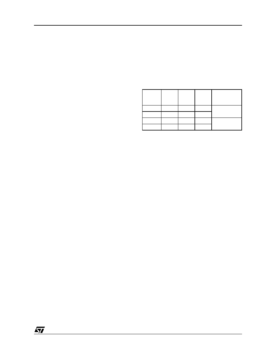
9.5 ACTIVE HALT MODE
ACTIVE HALT mode is the lowest power con-
sumption mode of the MCU with a real time clock
(RTC) available. It is entered by executing the
‘HALT’ instruction. The decision to enter either in
ACTIVE HALT or HALT mode is given by the LTC-
SR/ATCSR register status as shown in the follow-
ing table:.
The MCU can exit ACTIVE HALT mode on recep-
tion of a specific interrupt (see Table 6, “Interrupt
Mapping,” on page 36) or a RESET.
– When exiting ACTIVE HALT mode by means of
a RESET, a 256 CPU cycle delay occurs. After
the start up delay, the CPU resumes operation
by fetching the reset vector which woke it up (see
– When exiting ACTIVE HALT mode by means of
an interrupt, the CPU immediately resumes oper-
ation by servicing the interrupt vector which woke
it up (see Figure 27).
When entering ACTIVE HALT mode, the I bit in the
CC register is cleared to enable interrupts. There-
fore, if an interrupt is pending, the MCU wakes up
immediately (see Note 3).
In ACTIVE HALT mode, only the main oscillator
and the selected timer counter (LT/AT) are running
to keep a wake-up time base. All other peripherals
are not clocked except those which get their clock
supply from another clock generator (such as ex-
ternal or auxiliary oscillator).
Note: As soon as ACTIVE HALT is enabled, exe-
cuting a HALT instruction while the Watchdog is
active does not generate a RESET.
This means that the device cannot spend more
than a defined delay in this power saving mode.
LTCSR1
TB1IE bit
ATCSR
OVFIE1
bit
ATCSR
CK1 bit
ATCSR
CK0 bit
Meaning
0x
x
0
ACTIVE HALT
mode disabled
00
x
1x
x
ACTIVE HALT
mode enabled
x1
0
1
相关PDF资料 |
PDF描述 |
|---|---|
| ST7PL38F2UCXXXRE | 8-BIT, MROM, 8 MHz, MICROCONTROLLER, QCC20 |
| ST7PL39F2MA/XXXE | 8-BIT, MROM, 8 MHz, MICROCONTROLLER, PDSO20 |
| ST7L38F2UC/XXXE | 8-BIT, MROM, 8 MHz, MICROCONTROLLER, QCC20 |
| ST7FL38F2UATRE | 8-BIT, FLASH, 8 MHz, MICROCONTROLLER, QCC20 |
| ST7PL35F2MAXXXRE | 8-BIT, MROM, 8 MHz, MICROCONTROLLER, PDSO20 |
相关代理商/技术参数 |
参数描述 |
|---|---|
| ST7PLITE02F0U6TR | 制造商:STMICROELECTRONICS 制造商全称:STMicroelectronics 功能描述:8-BIT MICROCONTROLLER WITH SINGLE VOLTAGE FLASH MEMORY, DATA EEPROM, ADC, TIMERS, SPI |
| ST7PLITE02Y0B6 | 制造商:STMICROELECTRONICS 制造商全称:STMicroelectronics 功能描述:8-BIT MICROCONTROLLER WITH SINGLE VOLTAGE FLASH MEMORY, DATA EEPROM, ADC, TIMERS, SPI |
| ST7PLITE02Y0B6TR | 制造商:STMICROELECTRONICS 制造商全称:STMicroelectronics 功能描述:8-bit microcontroller with single voltage Flash memory, data EEPROM, ADC, timers, SPI |
| ST7PLITE02Y0M6 | 制造商:STMICROELECTRONICS 制造商全称:STMicroelectronics 功能描述:8-bit microcontroller with single voltage Flash memory, data EEPROM, ADC, timers, SPI |
| ST7PLITE02Y0M6TR | 制造商:STMICROELECTRONICS 制造商全称:STMicroelectronics 功能描述:8-bit microcontroller with single voltage Flash memory, data EEPROM, ADC, timers, SPI |
发布紧急采购,3分钟左右您将得到回复。