- 您现在的位置:买卖IC网 > PDF目录69378 > ST7PL38F2MC/XXXE (STMICROELECTRONICS) 8-BIT, MROM, 8 MHz, MICROCONTROLLER, PDSO20 PDF资料下载
参数资料
| 型号: | ST7PL38F2MC/XXXE |
| 厂商: | STMICROELECTRONICS |
| 元件分类: | 微控制器/微处理器 |
| 英文描述: | 8-BIT, MROM, 8 MHz, MICROCONTROLLER, PDSO20 |
| 封装: | 0.300 INCH, ROHS COMPLIANT, PLASTIC, SOP-20 |
| 文件页数: | 163/168页 |
| 文件大小: | 2955K |
| 代理商: | ST7PL38F2MC/XXXE |
第1页第2页第3页第4页第5页第6页第7页第8页第9页第10页第11页第12页第13页第14页第15页第16页第17页第18页第19页第20页第21页第22页第23页第24页第25页第26页第27页第28页第29页第30页第31页第32页第33页第34页第35页第36页第37页第38页第39页第40页第41页第42页第43页第44页第45页第46页第47页第48页第49页第50页第51页第52页第53页第54页第55页第56页第57页第58页第59页第60页第61页第62页第63页第64页第65页第66页第67页第68页第69页第70页第71页第72页第73页第74页第75页第76页第77页第78页第79页第80页第81页第82页第83页第84页第85页第86页第87页第88页第89页第90页第91页第92页第93页第94页第95页第96页第97页第98页第99页第100页第101页第102页第103页第104页第105页第106页第107页第108页第109页第110页第111页第112页第113页第114页第115页第116页第117页第118页第119页第120页第121页第122页第123页第124页第125页第126页第127页第128页第129页第130页第131页第132页第133页第134页第135页第136页第137页第138页第139页第140页第141页第142页第143页第144页第145页第146页第147页第148页第149页第150页第151页第152页第153页第154页第155页第156页第157页第158页第159页第160页第161页第162页当前第163页第164页第165页第166页第167页第168页
Obsolete
Product(s)
- Obsolete
Product(s)
ST7L34, ST7L35, ST7L38, ST7L39
94/168
LINSCI
SERIAL COMMUNICATION INTERFACE (SCI Mode) (cont’d)
11.5.5.6 Receiver Muting and Wake-up Feature
In multiprocessor configurations it is often desira-
ble that only the intended message recipient
should actively receive the full message contents,
thus reducing redundant SCI service overhead for
all non-addressed receivers.
The non-addressed devices may be placed in
sleep mode by means of the muting function.
Setting the RWU bit by software puts the SCI in
sleep mode:
All the reception status bits can not be set.
All the receive interrupts are inhibited.
A muted receiver may be woken up in one of the
following ways:
– by Idle Line detection if the WAKE bit is reset,
– by Address Mark detection if the WAKE bit is set.
Idle Line Detection
Receiver wakes up by Idle Line detection when the
Receive line has recognized an Idle Line. Then the
RWU bit is reset by hardware but the IDLE bit is
not set.
This feature is useful in a multiprocessor system
when the first characters of the message deter-
mine the address and when each message ends
by an idle line: As soon as the line becomes idle,
every receivers is waken up and analyse the first
characters of the message which indicates the ad-
dressed receiver. The receivers which are not ad-
dressed set RWU bit to enter in mute mode. Con-
sequently, they will not treat the next characters
constituting the next part of the message. At the
end of the message, an idle line is sent by the
transmitter: this wakes up every receivers which
are ready to analyse the addressing characters of
the new message.
In such a system, the inter-characters space must
be smaller than the idle time.
Address Mark Detection
Receiver wakes up by Address Mark detection
when it received a “1” as the most significant bit of
a word, thus indicating that the message is an ad-
dress. The reception of this particular word wakes
up the receiver, resets the RWU bit and sets the
RDRF bit, which allows the receiver to receive this
word normally and to use it as an address word.
This feature is useful in a multiprocessor system
when the most significant bit of each character
(except for the break character) is reserved for Ad-
dress Detection. As soon as the receivers re-
ceived an address character (most significant bit
= ’1’), the receivers are waken up. The receivers
which are not addressed set RWU bit to enter in
mute mode. Consequently, they will not treat the
next characters constituting the next part of the
message.
11.5.5.7 Parity Control
Hardware byte Parity control (generation of parity
bit in transmission and parity checking in recep-
tion) can be enabled by setting the PCE bit in the
SCICR1 register. Depending on the character for-
mat defined by the M bit, the possible SCI charac-
ter formats are as listed in Table 20.
Note: In case of wake-up by an address mark, the
MSB bit of the data is taken into account and not
the parity bit
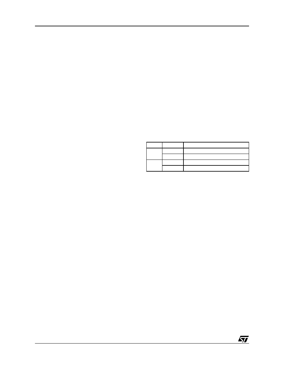
Table 20. Character Formats
Legend: SB = Start Bit, STB = Stop Bit,
PB = Parity Bit
Even parity: The parity bit is calculated to obtain
an even number of “1s” inside the character made
of the 7 or 8 LSB bits (depending on whether M is
equal to 0 or 1) and the parity bit.
Example: data = 00110101; 4 bits set => parity bit
will be 0 if even parity is selected (PS bit = 0).
Odd parity: The parity bit is calculated to obtain
an odd number of “1s” inside the character made
of the 7 or 8 LSB bits (depending on whether M is
equal to 0 or 1) and the parity bit.
Example: data = 00110101; 4 bits set => parity bit
will be 1 if odd parity is selected (PS bit = 1).
Transmission mode: If the PCE bit is set then the
MSB bit of the data written in the data register is
not transmitted but is changed by the parity bit.
Reception mode: If the PCE bit is set then the in-
terface checks if the received data byte has an
even number of “1s” if even parity is selected
(PS = 0) or an odd number of “1s” if odd parity is
selected (PS = 1). If the parity check fails, the PE
flag is set in the SCISR register and an interrupt is
generated if PCIE is set in the SCICR1 register.
M bit
PCE bit
Character format
0
| SB | 8 bit data | STB |
1
| SB | 7-bit data | PB | STB |
1
0
| SB | 9-bit data | STB |
1
| SB | 8-bit data | PB | STB |
1
相关PDF资料 |
PDF描述 |
|---|---|
| ST7PL38F2UCXXXRE | 8-BIT, MROM, 8 MHz, MICROCONTROLLER, QCC20 |
| ST7PL39F2MA/XXXE | 8-BIT, MROM, 8 MHz, MICROCONTROLLER, PDSO20 |
| ST7L38F2UC/XXXE | 8-BIT, MROM, 8 MHz, MICROCONTROLLER, QCC20 |
| ST7FL38F2UATRE | 8-BIT, FLASH, 8 MHz, MICROCONTROLLER, QCC20 |
| ST7PL35F2MAXXXRE | 8-BIT, MROM, 8 MHz, MICROCONTROLLER, PDSO20 |
相关代理商/技术参数 |
参数描述 |
|---|---|
| ST7PLITE02F0U6TR | 制造商:STMICROELECTRONICS 制造商全称:STMicroelectronics 功能描述:8-BIT MICROCONTROLLER WITH SINGLE VOLTAGE FLASH MEMORY, DATA EEPROM, ADC, TIMERS, SPI |
| ST7PLITE02Y0B6 | 制造商:STMICROELECTRONICS 制造商全称:STMicroelectronics 功能描述:8-BIT MICROCONTROLLER WITH SINGLE VOLTAGE FLASH MEMORY, DATA EEPROM, ADC, TIMERS, SPI |
| ST7PLITE02Y0B6TR | 制造商:STMICROELECTRONICS 制造商全称:STMicroelectronics 功能描述:8-bit microcontroller with single voltage Flash memory, data EEPROM, ADC, timers, SPI |
| ST7PLITE02Y0M6 | 制造商:STMICROELECTRONICS 制造商全称:STMicroelectronics 功能描述:8-bit microcontroller with single voltage Flash memory, data EEPROM, ADC, timers, SPI |
| ST7PLITE02Y0M6TR | 制造商:STMICROELECTRONICS 制造商全称:STMicroelectronics 功能描述:8-bit microcontroller with single voltage Flash memory, data EEPROM, ADC, timers, SPI |
发布紧急采购,3分钟左右您将得到回复。