- 您现在的位置:买卖IC网 > PDF目录382582 > TFS100B3 (Vectron International, Inc.) VI SAW滤波器(VI SAW Filter) PDF资料下载
参数资料
| 型号: | TFS100B3 |
| 厂商: | Vectron International, Inc. |
| 英文描述: | VI SAW滤波器(VI SAW Filter) |
| 中文描述: | 六声滤波器(SAW滤波器六) |
| 文件页数: | 1/2页 |
| 文件大小: | 22K |
| 代理商: | TFS100B3 |
Apn100B3.doc
Ltp:
version 2.1
01.11.00
VI TELEFILTER
Application Note
TFS 100B3
1
/2
VI TELEFILTER
Potsdamer Strae 18
D 14 513 TELTOW / Germany
Tel: (+49) 3328 4784-52 / Fax: (+49) 3328 4784-30
E-Mail: tft@telefilter.com
VI TELEFILTER reserves the right to make changes to the product(s) and/or information contained herein without notice. No liability is
assumed as a result of their use or application. No rights under any patent accompany the sale of any such product(s) or information.
Vectron International, Inc.
267 Lowell Road
Hudson, NH 03051 / USA
Tel: (603) 598-0070 Fax: (603) 598-0075
E-Mail: vti@vtinh.com
1. General
The filter can be driven in an unbalanced way. It is matched to
50
The matching element values given below are theoretical calculations based on measured values for
termination impedance, given in the specification and S-parameters of the filters on PCB. If there are
parasitics on the customer PCB, the matching elements have to be optimised regarding the circuit and
PCB design.
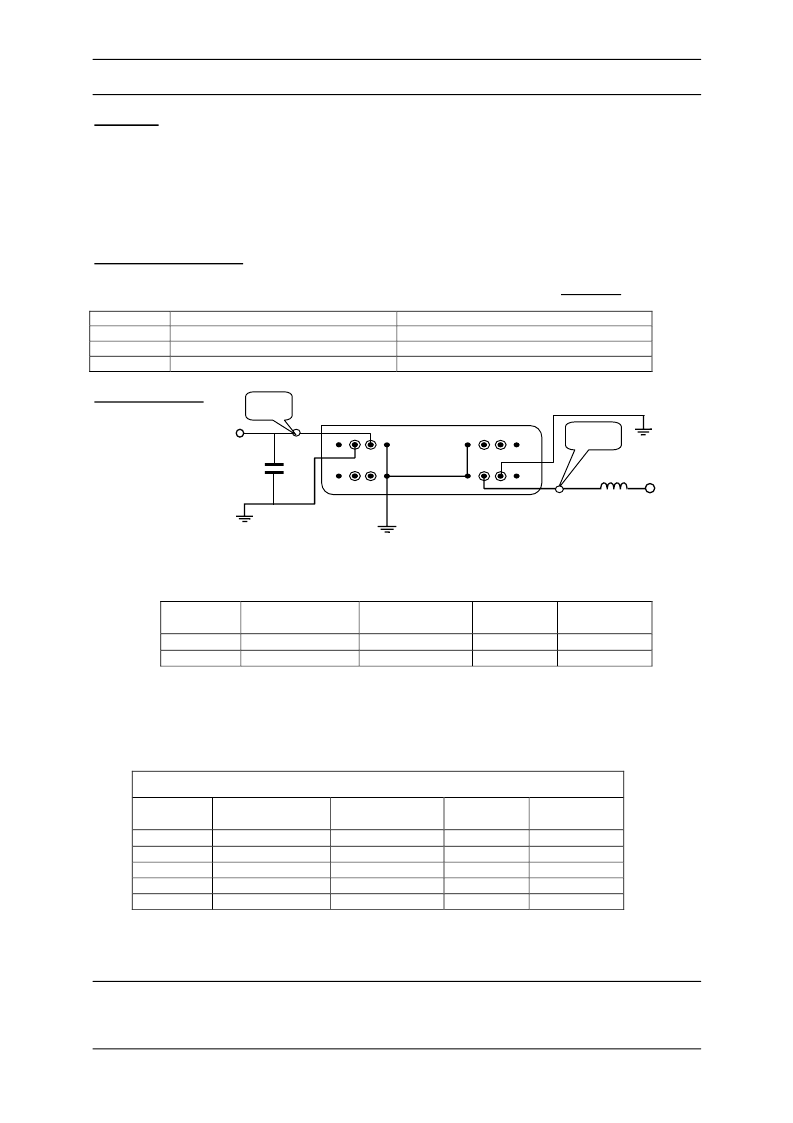
We have tested on the PCB one version of matching network: unbalanced (scheme 1).
2. Theoretical matching
The unbalanced driven source and load termination impedances of the filter for Scheme 1 are:
Frequency
Source termination impedance [
Zin
]
95 MHz
50
12 pF......44,32
- j 15,87
100 MHz
50
12 pF 43,78
- j 16,50
105 MHz
50
12 pF 43,23
- j 17,11
2.1
Scheme 1
The values of the matching elements, which are given below, are calculated from the source and load
impedance for ideal Q-value of the matching elements. If the values of the matching elements are not
equal to standard values, the best standard values are given in brackets.
The calculation was made without consideration of parasitics.
ILo (specification) = - max. 25 dB
Input
value (theor.)
value (theor.)
Q-value
C
1
[pF]
L
1
[nH]
∞
12,0
80 [82]
The values of the matching elements, which are given below, are calculated with consideration of the
different Q-values of the matching elements and different parasitics capacities and based on measured
S-parameters of the filter TFS 100B. We shall not take over any guarantee for achieving the typical
and limit values of the specification parameters as long as termination impedance differs from the
stated above.
Based on measured S-parameters
we calculated the following theoretical matching components
Input
value (theor.)
value (theor.)
Q-value
C
1
[pF]
L
1
[nH]
∞
12
80 [82]
100
12
80 [82]
70
12
80 [82]
70
8,2
80 [82]
Load termination impedance [
Zout
]
95,60
- 16,734 pF 50
+ j 47,75
100,54
- 15,915 pF 50
+ j 50,27
105,71
- 15,135 pF 50
+ j 52,78
Output
ILo
Max. ripple
In PB
[dB]
0,9
[dB]
-23,5
Output
ILo
Max. ripple
In PB
[dB]
0,9
0,9
0,9
0,9
[dB]
-23,5
-24,5
-25,5
-24,5
1 2 3 4 9 12
24 21 16 15 14 13
Z
out
C
1
L
1
Z
in
相关PDF资料 |
PDF描述 |
|---|---|
| TFS100B | VI SAW Filter(VI SAW滤波器(输入电阻:77.40Ω/-3.218pF,输出电阻:77.40Ω/-3.218pF)) |
| TFS100F | VI SAW滤波器(VI SAW Filter) |
| TFS110B | VI SAW滤波器(VI SAW Filter) |
| TFS110C | VI SAW滤波器(VI SAW Filter) |
| TFS110F | VI SAW Filter(VI SAW滤波器(输入电阻:890Ω/-5.6pF,输出电阻:680Ω/-5.9pF)) |
相关代理商/技术参数 |
参数描述 |
|---|---|
| TFS100C | 制造商:VECTRON 制造商全称:Vectron International, Inc 功能描述:Preliminary Specification |
| TFS100F | 制造商:VECTRON 制造商全称:Vectron International, Inc 功能描述:Filter Specification |
| TFS101 | 制造商:VECTRON 制造商全称:Vectron International, Inc 功能描述:SAW-Filter Specification |
| TFS1068 | 制造商:VECTRON 制造商全称:Vectron International, Inc 功能描述:Filter specification |
| TFS107 | 制造商:VECTRON 制造商全称:Vectron International, Inc 功能描述:VI TELEFILTER |
发布紧急采购,3分钟左右您将得到回复。