- 您现在的位置:买卖IC网 > PDF目录202172 > V55C3256164VGLK-7HPC (PROMOS TECHNOLOGIES INC) SYNCHRONOUS DRAM, PBGA54 PDF资料下载
参数资料
| 型号: | V55C3256164VGLK-7HPC |
| 厂商: | PROMOS TECHNOLOGIES INC |
| 元件分类: | DRAM |
| 英文描述: | SYNCHRONOUS DRAM, PBGA54 |
| 封装: | GREEN, MO-210, FBGA-54 |
| 文件页数: | 9/55页 |
| 文件大小: | 711K |
| 代理商: | V55C3256164VGLK-7HPC |
第1页第2页第3页第4页第5页第6页第7页第8页当前第9页第10页第11页第12页第13页第14页第15页第16页第17页第18页第19页第20页第21页第22页第23页第24页第25页第26页第27页第28页第29页第30页第31页第32页第33页第34页第35页第36页第37页第38页第39页第40页第41页第42页第43页第44页第45页第46页第47页第48页第49页第50页第51页第52页第53页第54页第55页
17
V55C3256164VG Rev. 1.0 September 2008
ProMOS TECHNOLOGIES
V55C3256164VG
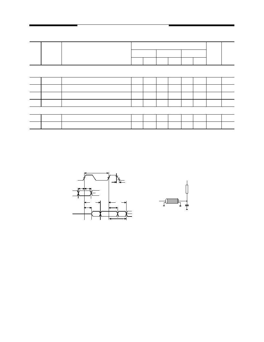
Notes for AC Parameters:
1.
For proper power-up see the operation section of this data sheet.
2.
AC timing tests have VIL = 0.8V and VIH = 2.0V with the timing referenced to the 1.4 V crossover point. The transition
time is measured between VIH and VIL. All AC measurements assume tT = 1ns with the AC output load circuit shown
in Figure 1.
3.
If clock rising time is longer than 1 ns, a time (tT/2 – 0.5) ns has to be added to this parameter.
4.
If tT is longer than 1 ns, a time (tT – 1) ns has to be added to this parameter.
5.
These parameter account for the number of clock cycle and depend on the operating frequency of the clock, as
follows:
the number of clock cycle = specified value of timing period (counted in fractions as a whole number)
Self Refresh Exit is a synchronous operation and begins on the 2nd positive clock edge after CKE returns high.
Self Refresh Exit is not complete until a time period equal to tRC is satisfied once the Self Refresh Exit command
is registered.
6.
Referenced to the time which the output achieves the open circuit condition, not to output voltage levels.
7. For TA = -40 to 105o C (H grade) / -40 to 125o C (Extended grade).
8. These parameter depend on output loading. Specified values are obtained with output open.
9. H grade / Extended grade does not guarantee Self-refresh current (ICC6).
Read Cycle
24
tOH
Data Out Hold Time
2.5
–
3
–
3
–
ns
2
25
tLZ
Data Out to Low Impedance Time
1
–
1
–
1
–
ns
26
tHZ
Data Out to High Impedance Time
3
6
3
7
3
7
ns
6
27
tDQZ
DQM Data Out Disable Latency
–
2
–
2
–
2
CLK
Write Cycle
28
tWR
Write Recovery Time for Auto precharge
2
–
2
–
2
–
CLK
29
tDQW
DQM Write Mask Latency
0
–
0
–
0
–
CLK
#
Symbol
Parameter
Limit Values
Unit
Note
-6
-7PC
-7
Min.
Max.
Min.
Max.
Min.
Max.
1.4V
tIS
tIH
tAC
tLZ
tOH
tHZ
CLK
COMMAND
OUTPUT
50 pF
I/O
Z=50 Ohm
+ 1.4 V
50 Ohm
VIH
VIL
tT
Figure 1.
tCK
相关PDF资料 |
PDF描述 |
|---|---|
| V580MC04 | VCO, 850 MHz - 890 MHz |
| V707S001 | VCO, 500 MHz - 1000 MHz |
| V706S001 | VCO, 600 MHz - 1200 MHz |
| V583ME02 | VCO, 985 MHz - 1060 MHz |
| V580ME04 | VCO, 910 MHz - 1000 MHz |
相关代理商/技术参数 |
参数描述 |
|---|---|
| V55HD | 制造商:Bugera 功能描述:55 WATT GUITAR AMPLIFIER 2 CHANNEL TUBE HEAD |
| V55MLA0402LN | 制造商:LITTELFUSE 制造商全称:Littelfuse 功能描述:Varistor Products Surface Mount Multilayer Varistors (MLVs) > MLA Series |
| V55MLA0402N | 制造商:LITTELFUSE 制造商全称:Littelfuse 功能描述:Varistor Products Surface Mount Multilayer Varistors (MLVs) > MLA Series |
| V55MLA0603H | 制造商:Littelfuse 功能描述: |
| V55MLA0603LN4 | 制造商:LITTELFUSE 制造商全称:Littelfuse 功能描述:Varistor Products Surface Mount Multilayer Varistors (MLVs) > MLA Series |
发布紧急采购,3分钟左右您将得到回复。