- 您现在的位置:买卖IC网 > PDF目录300164 > ZL50418GKG2 (ZARLINK SEMICONDUCTOR INC) DATACOM, LAN SWITCHING CIRCUIT, PBGA553 PDF资料下载
参数资料
| 型号: | ZL50418GKG2 |
| 厂商: | ZARLINK SEMICONDUCTOR INC |
| 元件分类: | 网络接口 |
| 英文描述: | DATACOM, LAN SWITCHING CIRCUIT, PBGA553 |
| 封装: | 37.50 X 37.50 MM, 2.33 MM HEIGHT, LEAD FREE, MS-034, HSBGA-553 |
| 文件页数: | 95/155页 |
| 文件大小: | 1928K |
| 代理商: | ZL50418GKG2 |
第1页第2页第3页第4页第5页第6页第7页第8页第9页第10页第11页第12页第13页第14页第15页第16页第17页第18页第19页第20页第21页第22页第23页第24页第25页第26页第27页第28页第29页第30页第31页第32页第33页第34页第35页第36页第37页第38页第39页第40页第41页第42页第43页第44页第45页第46页第47页第48页第49页第50页第51页第52页第53页第54页第55页第56页第57页第58页第59页第60页第61页第62页第63页第64页第65页第66页第67页第68页第69页第70页第71页第72页第73页第74页第75页第76页第77页第78页第79页第80页第81页第82页第83页第84页第85页第86页第87页第88页第89页第90页第91页第92页第93页第94页当前第95页第96页第97页第98页第99页第100页第101页第102页第103页第104页第105页第106页第107页第108页第109页第110页第111页第112页第113页第114页第115页第116页第117页第118页第119页第120页第121页第122页第123页第124页第125页第126页第127页第128页第129页第130页第131页第132页第133页第134页第135页第136页第137页第138页第139页第140页第141页第142页第143页第144页第145页第146页第147页第148页第149页第150页第151页第152页第153页第154页第155页
ZL50418
Data Sheet
44
Zarlink Semiconductor Inc.
The format of the Control Frame is described in the processor interface application note.
3.3
Unmanaged Mode
In unmanaged mode, the ZL50418 can be configured by EEPROM (24C02 or compatible) via an I2C interface at
boot time, or via a synchronous serial interface during operation.
3.3.1
I2C Interface
The IC interface serves the function of configuring the ZL50418 at boot time. The master is the ZL50418, and the
slave is the EEPROM memory.
The I2C interface uses two bus lines, a serial data line (SDA) and a serial clock line (SCL). The SCL line carries the
control signals that facilitate the transfer of information from EEPROM to the switch. Data transfer is 8-bit serial and
bidirectional at 50 Kbps. Data transfer is performed between master and slave IC using a request /
acknowledgment style of protocol. The master IC generates the timing signals and terminates data transfer. Figure
7 depicts the data transfer format. The slave address is the memory address of the EEPROM. Refer to “Register
Definition” on page 75 for IC address for each register.
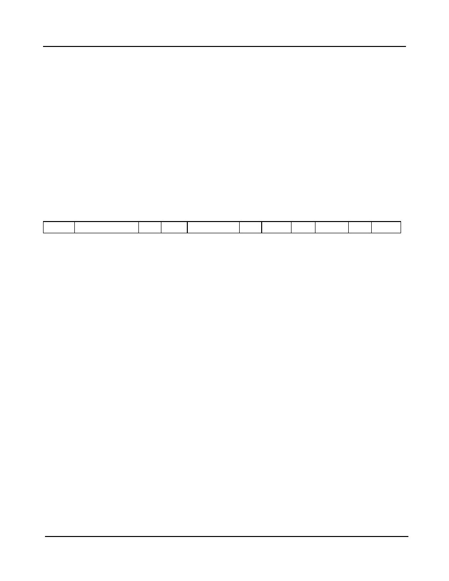
Figure 7 - Data Transfer Format for I2C Interface
3.3.1.1
Start Condition
Generated by the master (in our case, the ZL50418). The bus is considered to be busy after the Start condition is
generated. The Start condition occurs if while the SCL line is High, there is a High-to-Low transition of the SDA line.
Other than in the Start condition (and Stop condition), the data on the SDA line must be stable during the High
period of SCL. The High or Low state of SDA can only change when SCL is Low. In addition, when the I2C bus is
free, both lines are High.
3.3.1.2
Address
The first byte after the Start condition determines which slave the master will select. The slave in our case is the
EEPROM. The first seven bits of the first data byte make up the slave address.
3.3.1.3
Data Direction
The eighth bit in the first byte after the Start condition determines the direction (R/W) of the message. A master
transmitter sets this bit to W; a master receiver sets this bit to R.
3.3.1.4
Acknowledgment
Like all clock pulses, the acknowledgment-related clock pulse is generated by the master. However, the transmitter
releases the SDA line (High) during the acknowledgment clock pulse. Furthermore, the receiver must pull down the
SDA line during the acknowledge pulse so that it remains stable Low during the High period of this clock pulse. An
acknowledgment pulse follows every byte transfer.
If a slave receiver does not acknowledge after any byte, then the master generates a Stop condition and aborts the
transfer.
If a master receiver does not acknowledge after any byte, then the slave transmitter must release the SDA line to let
the master generate the Stop condition.
START
SLAVE ADDRESS
R/W
ACK
DATA 1 (8 bits)
ACK
DATA 2
ACK
DATA M
ACK
STOP
相关PDF资料 |
PDF描述 |
|---|---|
| ZLW-2-B | 1 MHz - 1000 MHz RF/MICROWAVE DOUBLE BALANCED MIXER, 9.5 dB CONVERSION LOSS-MAX |
| ZMG71W | SINGLE COLOR LED, GREEN |
| ZMM5228/D1 | 3.9 V, 0.5 W, SILICON, UNIDIRECTIONAL VOLTAGE REGULATOR DIODE |
| ZMM5242/D1 | 12 V, 0.5 W, SILICON, UNIDIRECTIONAL VOLTAGE REGULATOR DIODE |
| ZMV934ATC | VHF BAND, 12 V, SILICON, HYPERABRUPT VARIABLE CAPACITANCE DIODE |
相关代理商/技术参数 |
参数描述 |
|---|---|
| ZL51B | 制造商:YEASHIN 制造商全称:YEASHIN 功能描述:500 mW DO-35 Hermetically Sealed Glass Zener Voltage Regulators |
| ZL56B | 制造商:YEASHIN 制造商全称:YEASHIN 功能描述:500 mW DO-35 Hermetically Sealed Glass Zener Voltage Regulators |
| ZL5V1B | 制造商:YEASHIN 制造商全称:YEASHIN 功能描述:500 mW DO-35 Hermetically Sealed Glass Zener Voltage Regulators |
| ZL5V6B | 制造商:YEASHIN 制造商全称:YEASHIN 功能描述:500 mW DO-35 Hermetically Sealed Glass Zener Voltage Regulators |
| ZL60001 | 制造商:ZARLINK 制造商全称:Zarlink Semiconductor Inc 功能描述:High speed 2.5 Gbps 850 nm VCSEL |
发布紧急采购,3分钟左右您将得到回复。