- 您现在的位置:买卖IC网 > PDF目录24938 > 0805YC103MA72A (AVX Corporation) General Specifications PDF资料下载
参数资料
| 型号: | 0805YC103MA72A |
| 厂商: | AVX Corporation |
| 英文描述: | General Specifications |
| 中文描述: | 一般规格 |
| 文件页数: | 7/20页 |
| 文件大小: | 338K |
| 代理商: | 0805YC103MA72A |
55
Effects of Mechanical Stress – High “K” dielectric
ceramic capacitors exhibit some low level piezoelectric
reactions under mechanical stress. As a general statement,
the piezoelectric output is higher, the higher the dielectric
constant of the ceramic. It is desirable to investigate this
effect before using high “K” dielectrics as coupling capaci-
tors in extremely low level applications.
Reliability – Historically ceramic capacitors have been one
of the most reliable types of capacitors in use today.
The approximate formula for the reliability of a ceramic
capacitor is:
L
o
=
V
t
X
T
t
Y
L
t
V
o
T
o
where
Lo = operating life
Tt = test temperature and
Lt = test life
To = operating temperature
Vt = test voltage
in °C
Vo = operating voltage
X,Y = see text
Historically for ceramic capacitors exponent X has been
considered as 3. The exponent Y for temperature effects
typically tends to run about 8.
A capacitor is a component which is capable of storing
electrical energy. It consists of two conductive plates (elec-
trodes) separated by insulating material which is called the
dielectric. A typical formula for determining capacitance is:
C =
.224 KA
t
C = capacitance (picofarads)
K = dielectric constant (Vacuum = 1)
A = area in square inches
t = separation between the plates in inches
(thickness of dielectric)
.224 = conversion constant
(.0884 for metric system in cm)
Capacitance – The standard unit of capacitance is the
farad. A capacitor has a capacitance of 1 farad when 1
coulomb charges it to 1 volt. One farad is a very large unit
and most capacitors have values in the micro (10-6), nano
(10-9) or pico (10-12) farad level.
Dielectric Constant – In the formula for capacitance given
above the dielectric constant of a vacuum is arbitrarily cho-
sen as the number 1. Dielectric constants of other materials
are then compared to the dielectric constant of a vacuum.
Dielectric Thickness – Capacitance is indirectly propor-
tional to the separation between electrodes. Lower voltage
requirements mean thinner dielectrics and greater capaci-
tance per volume.
Area – Capacitance is directly proportional to the area of
the electrodes. Since the other variables in the equation are
usually set by the performance desired, area is the easiest
parameter to modify to obtain a specific capacitance within
a material group.
Energy Stored – The energy which can be stored in a
capacitor is given by the formula:
E = 12CV
2
E = energy in joules (watts-sec)
V = applied voltage
C = capacitance in farads
Potential Change – A capacitor is a reactive component
which reacts against a change in potential across it. This is
shown by the equation for the linear charge of a capacitor:
I
ideal =
C
dV
dt
where
I = Current
C = Capacitance
dV/dt = Slope of voltage transition across capacitor
Thus an infinite current would be required to instantly
change the potential across a capacitor. The amount of
current a capacitor can “sink” is determined by the above
equation.
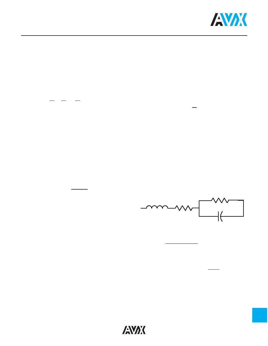
Equivalent Circuit – A capacitor, as a practical device,
exhibits not only capacitance but also resistance and
inductance. A simplified schematic for the equivalent circuit
is:
C = Capacitance
L = Inductance
Rs = Series Resistance
Rp = Parallel Resistance
Reactance – Since the insulation resistance (Rp) is normal-
ly very high, the total impedance of a capacitor is:
Z =
R2
S + (XC - XL )
2
where
Z = Total Impedance
R
s = Series Resistance
X
C = Capacitive Reactance
=
1
2
π fC
X
L = Inductive Reactance
= 2
π fL
The variation of a capacitor’s impedance with frequency
determines its effectiveness in many applications.
Phase Angle – Power Factor and Dissipation Factor are
often confused since they are both measures of the loss in
a capacitor under AC application and are often almost
identical in value. In a “perfect” capacitor the current in the
capacitor will lead the voltage by 90°.
General Description
R
L
R
C
P
S
相关PDF资料 |
PDF描述 |
|---|---|
| 0805YC103MA74A | SWITCH,SPST,100MA,4P,SMT |
| 0805Z104xxx | Circular Connector; Body Material:Aluminum; Series:PT06; No. of Contacts:21; Connector Shell Size:22; Connecting Termination:Solder; Circular Shell Style:Straight Plug; Circular Contact Gender:Pin; Insert Arrangement:22-21 |
| 0805ZC103JA72A | Circular Connector; MIL SPEC:MIL-C-5015; Body Material:Metal; Series:GT; No. of Contacts:4; Connector Shell Size:24; Connecting Termination:Solder; Circular Shell Style:Box Mount Receptacle; Body Style:Straight |
| 0805ZC103JA74A | GT 12C 12#12 SKT RECP |
| 0805ZC103KA72A | General Specifications |
相关代理商/技术参数 |
参数描述 |
|---|---|
| 0805YC103MAT2A | 功能描述:多层陶瓷电容器MLCC - SMD/SMT 16V 0.01uF 20% RoHS:否 制造商:American Technical Ceramics (ATC) 电容:10 pF 容差:1 % 电压额定值:250 V 温度系数/代码:C0G (NP0) 外壳代码 - in:0505 外壳代码 - mm:1414 工作温度范围:- 55 C to + 125 C 产品:Low ESR MLCCs 封装:Reel |
| 0805YC103MAT4A | 功能描述:多层陶瓷电容器MLCC - SMD/SMT 16volts 0.01uF 20% X7R RoHS:否 制造商:American Technical Ceramics (ATC) 电容:10 pF 容差:1 % 电压额定值:250 V 温度系数/代码:C0G (NP0) 外壳代码 - in:0505 外壳代码 - mm:1414 工作温度范围:- 55 C to + 125 C 产品:Low ESR MLCCs 封装:Reel |
| 0805YC104J4T2A | 功能描述:多层陶瓷电容器MLCC - SMD/SMT 16V 0.1uF 5% RoHS:否 制造商:American Technical Ceramics (ATC) 电容:10 pF 容差:1 % 电压额定值:250 V 温度系数/代码:C0G (NP0) 外壳代码 - in:0505 外壳代码 - mm:1414 工作温度范围:- 55 C to + 125 C 产品:Low ESR MLCCs 封装:Reel |
| 0805YC104J4Z2A | 功能描述:多层陶瓷电容器MLCC - SMD/SMT 16volts 0.1uF 5% X7R 0805 SIZE RoHS:否 制造商:American Technical Ceramics (ATC) 电容:10 pF 容差:1 % 电压额定值:250 V 温度系数/代码:C0G (NP0) 外壳代码 - in:0505 外壳代码 - mm:1414 工作温度范围:- 55 C to + 125 C 产品:Low ESR MLCCs 封装:Reel |
| 0805YC104JA72A | 功能描述:多层陶瓷电容器MLCC - SMD/SMT 16volts .1uF 5% RoHS:否 制造商:American Technical Ceramics (ATC) 电容:10 pF 容差:1 % 电压额定值:250 V 温度系数/代码:C0G (NP0) 外壳代码 - in:0505 外壳代码 - mm:1414 工作温度范围:- 55 C to + 125 C 产品:Low ESR MLCCs 封装:Reel |
发布紧急采购,3分钟左右您将得到回复。