- 您现在的位置:买卖IC网 > PDF目录30399 > 09330162772 RECTANGULAR CONNECTOR PDF资料下载
参数资料
| 型号: | 09330162772 |
| 元件分类: | 矩形连接器 |
| 英文描述: | RECTANGULAR CONNECTOR |
| 文件页数: | 1/1页 |
| 文件大小: | 101K |
| 代理商: | 09330162772 |
09 33 000 9954
03
.
22
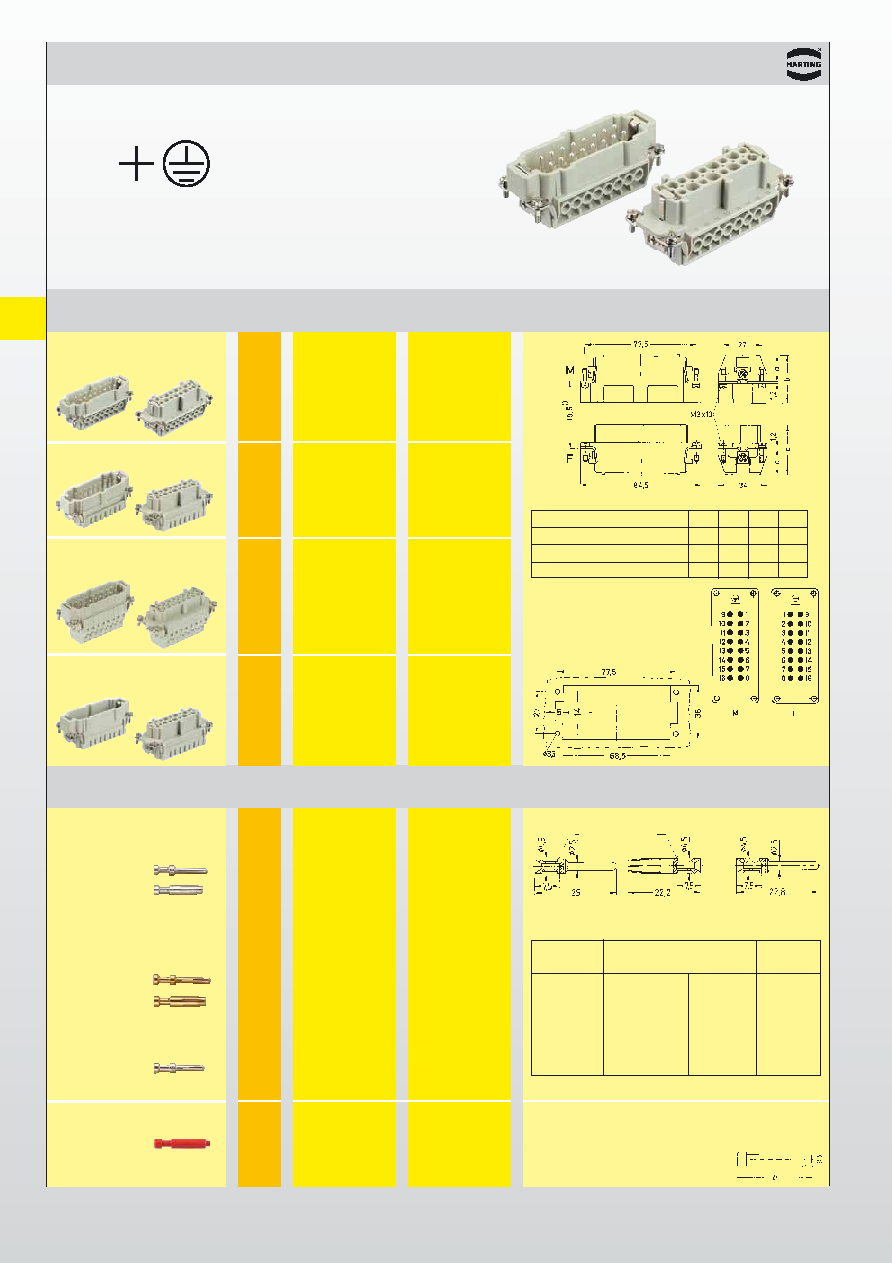
Han
E / EE
Han 16 E Han 16 ES Han 16 ESS
500 V
16 A
09 33 016 2601
09 33 016 2701
09 33 016 2616
09 33 016 2716
09 33 016 2602
09 33 016 2702
09 33 016 2672
09 33 016 2772
Inserts
Number of contacts
16
Part No.
Identification
Series
Male insert (M)
Female insert (F)
Drawing
Dimensions in mm
Size 16 B
Panel cut out for inserts for
use without hoods/housings
Contact arrangement
View from termination side
1)
Distance for contact max. 21 mm
Screw terminal
Han E
with wire protection
Cage-clamp terminal
Han ES
Crimp terminal
Han E
Order contacts separately
Cage-clamp terminal
Han ESS
two terminals per contact
ab
c
d
Han E screw
18
33
18
35
Han ES / Han E crimp
19
34
19
36
Han ESS
34
49
32
49
Wire gauge
Part No.
Identification
(mm2)
Male contacts
Female contacts
Drawing
Dimensions in mm
Crimp contacts
0.14-0.37
*09 33 000 6127*
*09 33 000 6227*
Power contacts
0.5
09 33 000 6121
09 33 000 6220
0.75
09 33 000 6114
09 33 000 6214
1.0
09 33 000 6105
09 33 000 6205
silver plated
1.5
09 33 000 6104
09 33 000 6204
2.5
09 33 000 6102
09 33 000 6202
3
09 33 000 6106
09 33 000 6206
4
09 33 000 6107
09 33 000 6207
0.14-0.37
*09 33 000 6117*
*09 33 000 6217*
0.5
09 33 000 6122
09 33 000 6222
0.75
09 33 000 6115
09 33 000 6215
gold plated
1.0
09 33 000 6118
09 33 000 6218
1.5
09 33 000 6116
09 33 000 6216
2.5
09 33 000 6123
09 33 000 6223
4.0
09 33 000 6119
09 33 000 6221
Relay contact
0.75-1
09 33 000 6109
silver plated
1.5
09 33 000 6110
2.5
09 33 000 6111
Stripping
Identification
Wire gauge
length
no groove
0.14-0.37 mm2 AWG 26-22
7,5 mm
no groove
0.5 mm2
AWG 20
7.5 mm
1 groove*
0.75 mm2
AWG 18
7.5 mm
1 groove
1.
mm2
AWG 18
7.5 mm
2 grooves
1.5 mm2
AWG 16
7.5 mm
3 grooves
2.5 mm2
AWG 14
7.5 mm
wide groove
3.0 mm2
AWG 12
7.5 mm
no groove
4.
mm2
AWG 12
7.5 mm
Operating contact
Identification
Crimp contact identification
* on the back crimp collar
Relay contact
Stock items in bold type
* only to be used with BUCHANAN crimping tool 09 99 000 0001
and adjustment gauge 09 99 000 0203
Coding Pin
To avoid accidental incorrect mating of adjacent connectors a coding
system is required. Coding is effected – by means of a code pin. For this rea-
son a female contact has to be inserted into the selected chamber.The code
pin has to be assembled into this contact from the
mating side. The opposite male contact is omitted.
相关PDF资料 |
PDF描述 |
|---|---|
| 09330162672 | RECTANGULAR CONNECTOR |
| 09330162601 | RECTANGULAR CONNECTOR |
| 09330162716 | RECTANGULAR CONNECTOR |
| 09330162616 | RECTANGULAR CONNECTOR |
| 09330162701 | RECTANGULAR CONNECTOR |
相关代理商/技术参数 |
参数描述 |
|---|---|
| 09330162782 | 功能描述:重负荷电源连接器 16P F. INSERT CRIMP HAN E RoHS:否 制造商:Hirose Connector 系列:PS2 产品类型:Connectors 位置/触点数量: 端接类型:Crimp 触点材料: 触点电镀:Gold 电压额定值: 电流额定值:300 A 附件类型: |
| 09330162788 | 功能描述:HAN 32ES - 16ES PRESS FEMALE INS 制造商:harting 系列:* 零件状态:在售 标准包装:1 |
| 09330162791 | 功能描述:重负荷电源连接器 FEMALE INSERT HAN 16E 16 POLES RoHS:否 制造商:Hirose Connector 系列:PS2 产品类型:Connectors 位置/触点数量: 端接类型:Crimp 触点材料: 触点电镀:Gold 电压额定值: 电流额定值:300 A 附件类型: |
| 09330164625 | 功能描述:重负荷电源连接器 HAN E AV 16P M SCREW TERMBLOCK LOWPRO RoHS:否 制造商:Hirose Connector 系列:PS2 产品类型:Connectors 位置/触点数量: 端接类型:Crimp 触点材料: 触点电镀:Gold 电压额定值: 电流额定值:300 A 附件类型: |
| 0933016462500 | 制造商:Harting Technology Group 功能描述:16way terminal insert w/male cont,Size6B |
发布紧急采购,3分钟左右您将得到回复。