- 您现在的位置:买卖IC网 > PDF目录90782 > 176L OP-AMP PDF资料下载
参数资料
| 型号: | 176L |
| 元件分类: | 运算放大器 |
| 英文描述: | OP-AMP |
| 文件页数: | 4/5页 |
| 文件大小: | 238K |
| 代理商: | 176L |
A
4
http://www.calex.com
2401 Stanwell Drive
Concord, CA 94520-4841
(510) 687-4411 Fax (510) 687-3333
CALEX
FaxFACTS:
320
1997
Model 178 DC Differential Amplifier
Description
Connections to the Model 178 are made as shown on the
mounting kit (Figure 11). The gain setting impedance can be
a fixed resistor or can be a potentiometer when variable gain
is needed. Input offset is adjusted by means of the 50 kohm
potentiometer between +15V and trim. If needed, common-
mode-rejection can be externally trimmed by connecting a
249
resistor between sense and out and a 500
potentiometer between ref (pin 10) and com. The MK278
mounting kit has provisions for adjusting offset and CMR on
the PC card.
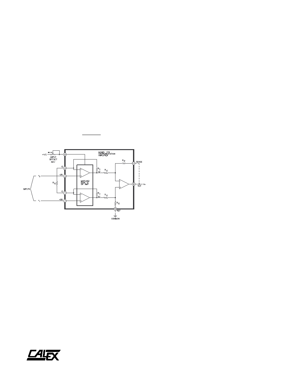
Theory of Operation
The Model 178 is a committed gain amplifier with high input
impedance looking into either input. A simplified block diagram
is shown in Figure 9. The input stage is a matched dual IC op
amp that is manufactured to CALEX specifications. The tight
matching of the two high performance input amplifiers and
their close physical proximity ensures excellent temperature
tracking and very good rejection of common mode inputs.
The output stage is a low-drift, low-noise IC op amp. Remote
sense and output reference terminals are provided at the
output stage. In most applications, the sense terminal is
simply connected to the amplifier output and the REF terminal
is connected to the system common as shown in Figure 9; but
these terminals can be used to externally trim CMR or to
develop current amplifier configurations. In addition, an output
offset can be applied to the amplifier by putting an offset
voltage on the REF terminal.
The overall gain equation is:
GAIN = 1 + 20 k
Rg
Input Offset Adjustment
With gain set at any desired level above 10, connect both
input leads (pins 2 and 3) to signal common (pin 6). Adjust the
input offset adj pot for zero at the amplifier output. Offset at
low gains is primarily due to offset of the output amplifier and
will be less than +1 mV. If the amplifier gain is to be varied over
a wide range, it is best to adjust input offset at the maximum
gain to be used. The MK278 mounting kit has provisions for
adjusting both offsets. With the amplifier connected for unity
gain (open circuit between pins L and S on the connector) and
the inputs connected to common, vary the output offset adj
pot for zero at the amplifier output. Then connect the amplifier
for the maximum gain of interest and adjust the offset by
varying the input offset adj. Repeat both adjustments if
necessary.
Output Offset
Offset of the output stage can be directly varied over a wide
range by disconnecting the ref input pin (pin 10) from common
and applying a voltage to the ref input. The output level can
be adjusted over a range of +10V independent of initial offset
adjustments. Source impedance of the offsetting voltage
must be very low in order to not degrade CMR. The impedance
at pin 10 is approximately 160 k
. For best results, the
offsetting voltage should be supplied through an operational
amplifier with low output impedance.
Gain Adjustment
The gain can be set by fixed resistors or a gain pot. Gain of
the Model 178 is deliberately trimmed to be low by 3% to 5%
for infinite RG, thus assuring that the amplifier can be set for
unity gain. This is valid even with the external CMR adjustment
circuit as shown in Figure 12. This makes the gain range
somewhat greater than the nominal range of 1 to 1000. Above
100, gain is primarily determined by the 20 k
/R
G term, which
is accurate to within ±0.2%. For Gain = 1, RG will be 400 K to
1 megohm.
Common Mode Rejection
The key advantage of using a differential input instrumentation
amplifier is its ability to reject common-mode inputs. The
common-mode input generally consists of a DC component
plus 60 Hz noise. To externally adjust CMR, connect the two
inputs together (pins 2 and 3) and apply a low frequency ±10V
sine wave. The gain should be set to the lowest value that will
be used, then vary the CMR ADJ pot for minimum amplifier
output. The CMR is 20 log10 (Ad /Acm), where Ad is the
differential gain setting and A
cm is the undesired common-
mode gain. The Model 178 can be readily trimmed to CMR of
better than 120 dB at DC.
FIGURE 9. Simplified Circuit Diagram for Model 178
相关PDF资料 |
PDF描述 |
|---|---|
| 178 | OP-AMP |
| 1782-97H | 1 ELEMENT, 0.13 uH, PHENOLIC-CORE, GENERAL PURPOSE INDUCTOR |
| 1782-97F | 1 ELEMENT, 0.13 uH, PHENOLIC-CORE, GENERAL PURPOSE INDUCTOR |
| 1782-95F | 1 ELEMENT, 0.11 uH, PHENOLIC-CORE, GENERAL PURPOSE INDUCTOR |
| 1782-91H | 1 ELEMENT, 910 uH, FERRITE-CORE, GENERAL PURPOSE INDUCTOR |
相关代理商/技术参数 |
参数描述 |
|---|---|
| 176L0271 | 制造商:Amphenol Corporation 功能描述: |
| 176L0378 | 制造商:Amphenol Corporation 功能描述: |
| 176P1000A | 制造商:未知厂家 制造商全称:未知厂家 功能描述:Industrial Control IC |
| 176P1000S | 制造商:未知厂家 制造商全称:未知厂家 功能描述:Industrial Control IC |
| 176P12 | 功能描述:电缆组件 MINI-MIZER RoHS:否 制造商:Molex 产品:Power Assemblies 类型:Cable Assembly 连接器端口 A:No Connector 连接器端口 A 管脚计数:4 连接器端口 B:No Connector 连接器端口 B 管脚计数: 型式:Male 线规 - 美国线规(AWG):20, 28 长度:0.305 m 颜色:Black, Red |
发布紧急采购,3分钟左右您将得到回复。