- 您现在的位置:买卖IC网 > PDF目录90917 > 1N4002S 1 A, 100 V, SILICON, SIGNAL DIODE PDF资料下载
参数资料
| 型号: | 1N4002S |
| 元件分类: | 二极管(射频、小信号、开关、功率) |
| 英文描述: | 1 A, 100 V, SILICON, SIGNAL DIODE |
| 封装: | ROHS COMPLIANT, PLASTIC, A-405, 2 PIN |
| 文件页数: | 1/2页 |
| 文件大小: | 61K |
| 代理商: | 1N4002S |
PAGE . 1
July 22,2010-REV.02
1N4001S~1N4007S
FEATURES
Low forward voltage drop
High current capability
High reliability
High surge current capability
Exceeds environmental standards of MIL-S-19500/228
In compliance with EU RoHS 2002/95/EC directives
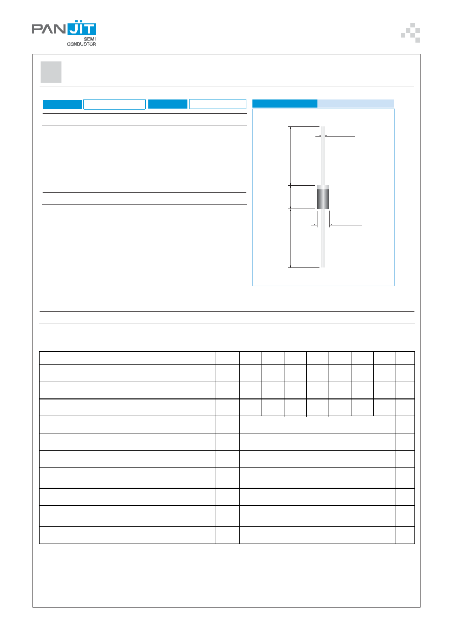
MECHANICAL DATA
Case: A-405 Molded plastic
Epoxy: UL 94V-O rate flame retardant.
Lead: Axial leads, solderable per MIL-STD-750, Method 2026
Polarity: Color band denotes cathode end
Mounting Position: Any
Weight: 0.008 ounces, 0.22 gram
PLASTIC SILICON RECTIFIERS
NOTES:
1. Measured at 1 MHz and applied reverse voltage of 4.0 VDC.
2. Thermal Resistance from Junction to Ambient and from junction to lead at 0.375”(9.5mm)lead length P.C.B.mounted.
.025(.64)
.107(2.7)
.021(.53)
.080(2.0)
1.
0(
25
.4
)M
IN
.
1.
0(
25
.4
)M
IN
.
.20
5(
5.
2)
.16
0(
4.
1)
A-405
Unit: inch(mm)
VOLTAGE
50 to 1000 Volts
CURRENT
1.0 Amperes
MAXIMUM RATINGS AND ELECTRICAL CHARACTERISTICS
Ratings at 25°C ambient temperature unless otherwise specified. Single phase, half wave, 60 Hz, resistive or inductive load.
For capacitive load,derate current by 20%.
PA RA M E TE R
S YM B OL 1N4001S 1N4002S 1 N4003S 1N4004S 1N4005S 1N4006S 1N4007S UNITS
M a xi m um Re curre nt P eak Re ve rs e Vo ltage
V
RRM
50
10 0
200
400
600
800
1000
V
Ma xi mum RM S Vo lta g e
V
RMS
35
70
140
280
420
560
700
V
Ma xi mum D C B lo c k i ng Vo lta g e
V
DC
50
10 0
200
400
600
800
1000
V
M a xi m um A verage Forward C ur rent .375 " (9.5m m ) lead le ng th at
T
A =7 5
OC
I
F(AV )
1.0
A
P eak Fo rward S urge C ur rent : 8.3m s si ng le ha lf si ne -wave
superi m posed on ra te d load (J E D E C m e thod)
I
FS M
30
A
M a xi m um Forward Vo ltage at 1.0A
V
F
1.1
V
M a xi m um D C Re ve r s e C ur rent at Ra ted D C B loc ki ng
Vo ltage
T
J=2 5
OC
T
J= 100
OC
I
R
5.0
500
μA
Typi cal Junc ti on c apa c i ta nc e (Note 1)
C
J
15
pF
Typi cal Therm a l Re si s tance (Note 2)
R
θJA
R
θJC
R
θJL
50
25
17
OC /
W
Operati ng Junc ti on and S torage Te mp e rature Ra ng e
T
J ,T STG
-55 to +150
OC
相关PDF资料 |
PDF描述 |
|---|---|
| 1N4004S | 1 A, 400 V, SILICON, SIGNAL DIODE |
| 1N4002W | 1 A, 100 V, SILICON, SIGNAL DIODE |
| 1N4003W | 1 A, 200 V, SILICON, SIGNAL DIODE |
| 1N4006W | 1 A, 800 V, SILICON, SIGNAL DIODE |
| 1N4007W | 1 A, 1000 V, SILICON, SIGNAL DIODE |
相关代理商/技术参数 |
参数描述 |
|---|---|
| 1N4002S _AY _10001 | 制造商:PanJit Touch Screens 功能描述: |
| 1N4002S R0 | 制造商:SKMI/Taiwan 功能描述:Diode 100V 1A 2-Pin Case A-405 T/R |
| 1N4002S_ R2 _10001 | 制造商:PanJit Touch Screens 功能描述: |
| 1N4002SG | 功能描述:整流器 1500W 20V 5% UNI TRANSZORB-TVS RoHS:否 制造商:Vishay Semiconductors 产品:Standard Recovery Rectifiers 配置: 反向电压:100 V 正向电压下降: 恢复时间:1.2 us 正向连续电流:2 A 最大浪涌电流:35 A 反向电流 IR:5 uA 安装风格:SMD/SMT 封装 / 箱体:DO-221AC 封装:Reel |
| 1N4002SG R0 | 制造商:SKMI/Taiwan 功能描述:Diode 100V 1A 2-Pin Case A-405 T/R |
发布紧急采购,3分钟左右您将得到回复。