- 您现在的位置:买卖IC网 > PDF目录90990 > 1N5395 1.5 A, 400 V, SILICON, RECTIFIER DIODE, DO-15 PDF资料下载
参数资料
| 型号: | 1N5395 |
| 元件分类: | 整流器 |
| 英文描述: | 1.5 A, 400 V, SILICON, RECTIFIER DIODE, DO-15 |
| 文件页数: | 1/2页 |
| 文件大小: | 55K |
| 代理商: | 1N5395 |
MAXIMUM RATINGS& ELECTRICAL CHARACTERISTICS
FEATURES
Data Sheet No. GPDP-151-1B
MECHANICAL SPECIFICATION
Ratings at 25 °C ambient temperature unless otherwise specified.
Single phase, half wave, 60Hz, resistive or inductive load.
For capacitive loads, derate current by 20%.
Tel.: (310) 767-1052
Fax: (310) 767-7958
DIOTEC ELECTRONICS CORP.
Gardena, CA 90248
U.S.A
18020 Hobart Blvd., Unit B
Average Forward Rectified Current@ T = 75 C,
Lead length= 0.375 in. (9.5 mm)
A
o
PARAMETER (TEST CONDITIONS)
Maximum DC Blocking Voltage
Peak Forward Surge Current( 8.3 mSec single half sine wave
superimposed on rated load)
Maximum Forward Voltage at 1.5 Amps DC
Typical Thermal Resistance, Junction to Ambient (Note 1)
Operating and Storage Temperature Range
Maximum Average DC Reverse Current
At Rated DC Blocking Voltage
Maximum Peak Recurrent Reverse Voltage
Maximum RMS Voltage
Series Number
IRM
IRM(AV)
R
θJA
T T
J,
STG
IO
VRMS
VRRM
VRM
SYMBOL
RATINGS
VOLTS
°C/W
°C
AMPS
UNITS
VOLTS
A
VFM
IFSM
Typical Junction Capacitance (Note 2)
CJ
pF
200
400
140
280
200
800
560
800
400
1.5
60
1
30
5
50
30
-65 to +175
4.97fgpdp151
(1) Lead length= 0.375 in. (9.5 mm)
(2) Measured at 1MHz& applied reverse voltage of4 volts
NOTES:
@ T= 25 C
A
o
@ T = 100 C
A
o
Low cost
Low leakage
Low forward voltage drop
High current capacity
Easily cleaned with freon, alcohol, chlorothene and similar
solvents
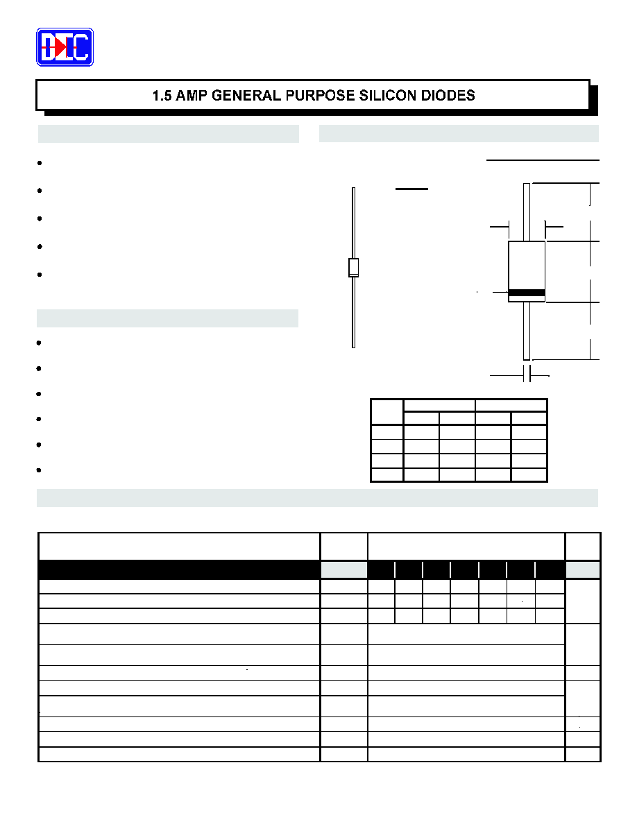
Case: JEDEC DO-15 molded plastic (U/L Flammability Rating 94V-0)
Terminals: Plated axial leads
Soldering: Per MIL-STD 202 Method 208 guaranteed
Polarity: Color band denotes cathode
Mounting Position: Any
Weight: 0.01 Ounces (0.4 Grams)
H9
MECHANICAL DATA
ACTUAL SIZE OF
DO-15 PACKAGE
Sym
In
mm
Minimum
Maximum
BL
BD
LL
LD
1.00
0.028
In
mm
0.140
0.255
0.034
6.48
3.6
0.86
0.240
0.130
25.4
0.71
6.01
3.3
Color Band
Denotes
Cathode
LD (Dia)
BD (Dia)
LL
BL
LL
Maximum Full Cycle Reverse Current@ T = 75 C (Note 1)
L
o
1N5391 1N5392 1N5393 1N5395 1N5397 1N5398 1N5399
50
35
50
100
70
100
600
420
600
1000
700
1000
SERIES 1N5391- 1N5399
DO- 15
相关PDF资料 |
PDF描述 |
|---|---|
| 1N5397 | 1.5 A, 600 V, SILICON, RECTIFIER DIODE, DO-15 |
| 1N5399 | 1.5 A, 1000 V, SILICON, RECTIFIER DIODE, DO-15 |
| 1N5398S | 1.5 A, 800 V, SILICON, RECTIFIER DIODE, DO-41 |
| 1N5399S | 1.5 A, 1000 V, SILICON, RECTIFIER DIODE, DO-41 |
| 1N5398 | 1.5 A, 800 V, SILICON, RECTIFIER DIODE, DO-15 |
相关代理商/技术参数 |
参数描述 |
|---|---|
| 1N5395 _AY _10001 | 制造商:PanJit Touch Screens 功能描述: |
| 1N5395 | 制造商:Fairchild Semiconductor Corporation 功能描述:Bridge Rectifier |
| 1N5395/23 | 制造商:Vishay Angstrohm 功能描述:Diode Switching 400V 1.5A 2-Pin DO-204AL Ammo |
| 1N5395_ R2 _10001 | 制造商:PanJit Touch Screens 功能描述: |
| 1N5395_Q | 功能描述:整流器 1.5a Rectifier General Purpose RoHS:否 制造商:Vishay Semiconductors 产品:Standard Recovery Rectifiers 配置: 反向电压:100 V 正向电压下降: 恢复时间:1.2 us 正向连续电流:2 A 最大浪涌电流:35 A 反向电流 IR:5 uA 安装风格:SMD/SMT 封装 / 箱体:DO-221AC 封装:Reel |
发布紧急采购,3分钟左右您将得到回复。