- 您现在的位置:买卖IC网 > PDF目录109716 > 20IMX7-05-9M (POWER-ONE INC) 1-OUTPUT 6.1 W DC-DC REG PWR SUPPLY MODULE PDF资料下载
参数资料
| 型号: | 20IMX7-05-9M |
| 厂商: | POWER-ONE INC |
| 元件分类: | 电源模块 |
| 英文描述: | 1-OUTPUT 6.1 W DC-DC REG PWR SUPPLY MODULE |
| 文件页数: | 12/15页 |
| 文件大小: | 213K |
| 代理商: | 20IMX7-05-9M |
IMX 7 DC/DC Series Data Sheet
7W Board Mountable Converter
REV. OCT 01, 2003
6/15
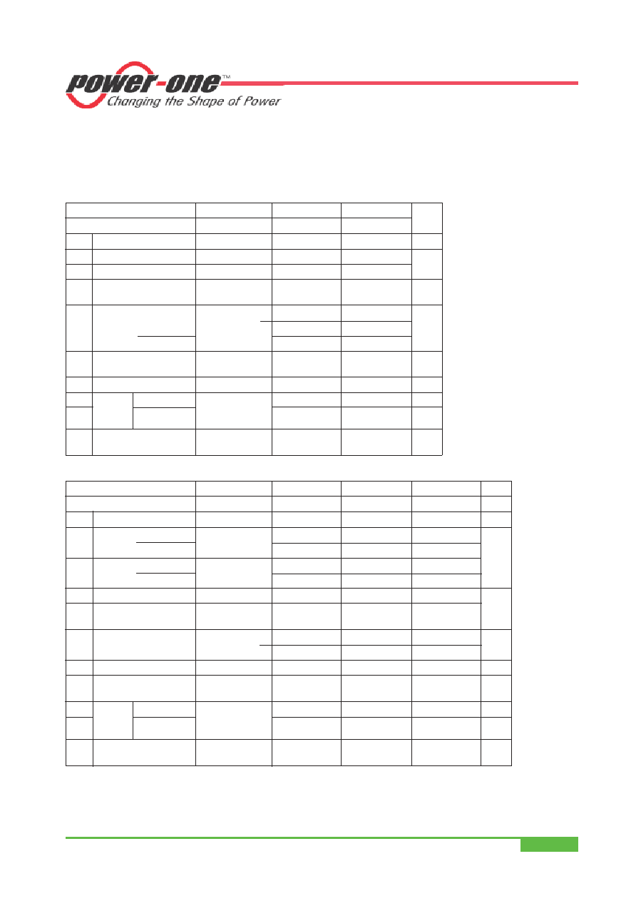
IMX SERIES
Electrical Output Data
General conditions:
–TA = 25°C, unless TC is specified.
– Connector pins i and Vi– interconnected.
– Trim or R input not connected.
Table 5a: Output data for single output units
Output
Vo nom
3.3 V
5.1 V
Characteristics
Conditions
min typ max
Unit
Vo1
Output voltage
Vi nom
3.28
3.32
5.07
5.13
VDC
Io nom Output current
Vi min...Vi max
1.5
1.2
A
Io L
Current limit 2
Vi nom, TC = 25°C
3.0
2.4
Vo
Line and load regulation
Vi min...Vi max
Io = (0.05...1) Io nom
±1
%
Vo1, 2 Output voltage noise
Vi min...Vi max
5
70
mVpp
20/40/70 IMX
Io = Io nom
6
20
40
20
40
110 IMX
40
50
40
50
Vo clp Output overvoltage
115
130
115
130
%
limitation 7
Co ext Admissible capacitive load
≤2500
≤2000
F
Vo d
Dynamic Voltage deviat. Vi nom
±250
mV
td
load
Recovery time
Io nom × 1/2 Io nom
11
ms
regulat
αVo
Temperature coefficient
Vi min...Vi max
Vo/TC (TC min...TC max)
Io = 0...Io max
±0.02
%/K
Table 5b: Output data for single output units
Output
Vo nom
12 V
15 V
24 V
Characteristics
Conditions
min typ max
Unit
Vo1
Output voltage
Vi nom
11.90
12.10 14.88
15.12 23.81
24.19
VDC
Io nom Output
20 IMX Vi min...Vi max
0.5
0.4
0.26
A
current 1 40/70/110 IMX
0.6
0.48
0.3
Io L
Current
20 IMX Vi nom, TC = 25°C
1.0
0.95
0.5
limit 2, 3 40/70/110 IMX
1.2
1.1
0.6
Vo
Line regulation
Vi min...Vi max, Io nom
±1
%
Vo l Load regulation 4
Vi nom
±3
Io = (0.1...1) Io nom
Vo1, 2 Output voltage noise
Vi min...Vi max
5
120
150
240
mVpp
Io = Io nom
6
25
50
30
60
50 100
Vo clp Output overvoltage limit. 7 Minimum load 1% 115
130
115
130
115
130
%
Co ext Admissible
≤300
≤200
≤100
F
capacitive load 3
Vo d
Dynamic Voltage deviat. Vi nom
±330
±350
±600
mV
td
load
Recovery time Io nom ×
1
/2 Io nom
11
1
ms
regulat.
αVo
Temperature coefficient
Vi min...Vi max
Vo/TC (TC min...TC max)
Io = 0...Io max
±0.02
%/K
1 Each output is capable of delivering full output power, Po nom according to table: Model Selection.
2 The current limit is primary side controlled.
3 Measured with both outputs connected in parallel.
4 Conditions for specified output. Other output loaded with constant current Io = 0.5 Io nom.
5 BW = 20 MHz
6 Measured with a probe according to EN 61204.
7 The overvoltage protection is not tracking with the R control.
相关PDF资料 |
PDF描述 |
|---|---|
| 20IMX7-0505-8C | 2-OUTPUT 6 W DC-DC REG PWR SUPPLY MODULE |
| 20IMX4-2424-8ZG | DC-DC REG PWR SUPPLY MODULE |
| 28IYR1-15-15-T | 2-OUTPUT 1 W DC-DC REG PWR SUPPLY MODULE |
| 20IMX7-12-12-8X | 2-OUTPUT 6 W DC-DC REG PWR SUPPLY MODULE |
| 20IMX7-12-12-9XM | 2-OUTPUT 6 W DC-DC REG PWR SUPPLY MODULE |
相关代理商/技术参数 |
参数描述 |
|---|---|
| 20IMX7-12-12-8 | 功能描述:DC/DC转换器 7W (2x 12V) DC Input (8.4-36V) RoHS:否 制造商:Murata 产品: 输出功率: 输入电压范围:3.6 V to 5.5 V 输入电压(标称): 输出端数量:1 输出电压(通道 1):3.3 V 输出电流(通道 1):600 mA 输出电压(通道 2): 输出电流(通道 2): 安装风格:SMD/SMT 封装 / 箱体尺寸: |
| 20IMX712128G | 制造商:Power-One 功能描述: |
| 20IMX7-12-12-8G | 功能描述:DC/DC转换器 RoHS:否 制造商:Murata 产品: 输出功率: 输入电压范围:3.6 V to 5.5 V 输入电压(标称): 输出端数量:1 输出电压(通道 1):3.3 V 输出电流(通道 1):600 mA 输出电压(通道 2): 输出电流(通道 2): 安装风格:SMD/SMT 封装 / 箱体尺寸: |
| 20IMX7-12-12-9 | 制造商:POWER-ONE 制造商全称:Power-One 功能描述:7 Watt DC-DC Converters |
| 20IMX7-12-8M | 制造商:Power-One 功能描述:DC/DC PS SGL-OUT 12V 0.6A 7.2W 9PIN - Bulk |
发布紧急采购,3分钟左右您将得到回复。