- 您现在的位置:买卖IC网 > PDF目录33511 > 4-1414915-9 (Tyco Electronics) Automotive Relays PDF资料下载
参数资料
| 型号: | 4-1414915-9 |
| 厂商: | Tyco Electronics |
| 元件分类: | 特殊继电器 |
| 英文描述: | Automotive Relays |
| 中文描述: | 汽车继电器 |
| 文件页数: | 1/3页 |
| 文件大小: | 591K |
| 代理商: | 4-1414915-9 |
06-2011, Rev. 0611
www.te.com
2011 Tyco Electronics Corporation,
a TE Connectivity Ltd. company.
Datasheets and product specification ac-
cording to IEC 61810-1 and to be used only
together with the ‘Definitions’ section.
Datasheets and product data is subject to the
terms of the disclaimer and all chapters of
the ‘Definitions’ section, available at
http://relays.te.com/definitions
Datasheets, product data, ‘Definitions’ sec-
tion, application notes and all specifications
are subject to change.
1
n
Reduced coil power consumption of latching version allows
higher limiting continuous current (50A) and increased ambient
temperature (125°C)
n
Maximum switch on current 200A
n
60% volume reduced Power K at increased performance
n
PCB area requirements minimized by 50% to only 293mm2
n
Size optimized to L x W x H 18.3x16x15.9mm
n
Design allows highest reliability
n
High shock and vibration resistance
n
No change of switching state version at breakdown of battery voltage
n
For monostable version refer to Power Relay PK2 (THT – THR)
Typical applications
Energy management, engine control, ignition, main switch/supply relay,
preheating system, quiescent current management.
Contact Data
Contact arrangement
1 form A, 1 NO
Rated voltage
12VDC
Rated current
50A1)
Limiting continuous current
23°C
50A1)
85°C
40A1)
125°C
30A1)
Limiting making current, pin 4-5, THT/THR
200A2)3)
Limiting breaking current, pin 4-5, THT/THR
40A2)
Contact material
AgSn02
Min. recommended contact load
1A at 5VDC4)
Initial voltage drop at 10A, typ./max.
30/300mV
Frequency of operation at nominal load
6 ops./min (0.1Hz)
Operate/release time
typ. 1.5ms
Electrical endurance
at cyclic temperature -40/+23/+85°C, 13.5VDC,
120ms (on), 4.88s (off),
motor load: L=0.5mH, 60A (on)/35A (off) >1x10⁵ ops.5)
resistive load: 40A (on)/40A (off)
>1x10⁵ ops.5)
capacitive load 200A (on)/20A (off)
>1x10⁵ ops.5)
Mechanical endurance
>2x10⁶ ops.
1) Measured on 70x70x1.5mm epoxy PCB FR4 with 52cm2 (double layer 140μm) copper
area. The load circuit shall withstand current applied until 40A ATO fuse blows.
2) The values apply to a resistive or inductive load with suitable spark suppression and at
maximum 13.5VDC for 12VDC load voltages.
3) Corresponds to a capacitive peak inrush current on initial actuation (cold filament).
4) See chapter Diagnostics of Relays in our Application Notes or consult the internet at
http://relays.te.com/appnotes/
5) Be aware of using right polarity, see Terminal Assignment. Wrong polarity will reduce
endurance.
Coil Data
Magnetic system
bistable (two coil system)
Coil voltage range
23°C (set - reset)
28/18VDC6)
Rated coil voltage
12VDC
Polarity for set/reset
set
reset
energization
-
+
-
+
pin 1
pin 6
pin 2
pin 6
Coil versions, bistable 2 coils
Coil
Rated
Set
Reset
Set/reset
Impulse
code
voltage
coil resistance
lenght
VDC
±10%
ms
004/006
12
6.9
20/19
10 – 100
All figures are given for coil without preenergization, at ambient temperature +23°C.
6) Overvoltage according to ISO 16750-2 functional status C. In case of a reset latch pulse
U>18VDC contact may reclose, but will not remain closed (no latching function). The
delay between driving impulses at cyclic energizing at TAmb=85°C must be at least 10s.
Insulation Data
Initial dielectric strength
between contact and coil
500VACrms
Other Data
EU RoHS/ELV compliance
compliant,
THT: sealed type washable
THR: sealed type vented
Ambient temperature
-40 to +125°C
Cold storage, IEC 60068-2-1
1000h; -40°C
Dry heat, IEC 60068-2-2
1000h; +125°C
Temperature cycling (shock),
IEC 60068-2-14, Na
1000 cycles, -40/+125°C,
dwell time 15min
Degree of protection
THT:
RT III (IEC 61810), IP67 (IEC 60529)
THR:
RT II (IEC 61810), IP56 (IEC 60529)
Sealing test, IEC 60068-2-17
THT:
Qc, method 2, 1min, 70°C
Vibration resistance (functional),
IEC 68-2-6 (sine pulse form), 30 to 440Hz,
no change in the switching stte >10μs
>20g
Shock resistance (functional), IEC 68-2-27 (half sine form single pulses)
open NO contact will not close >10μs
6ms >30g
closed NO contact will not open >10μs
11ms >100g
Power Relay PK2 Latching (THT – THR)
Automotive Relays
PCB Single Relays
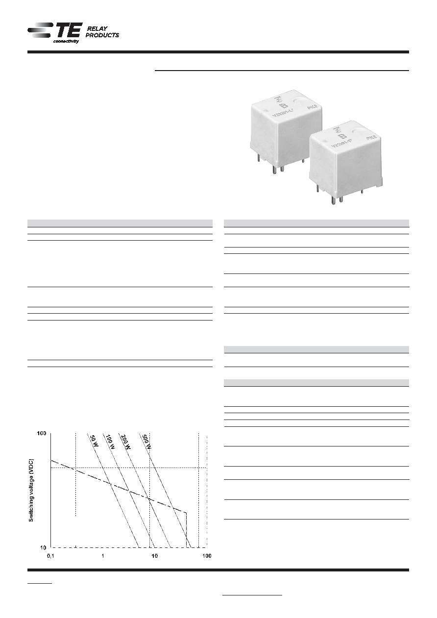
Max. DC load breaking capacity
Load limit curve: safe shutdown,
no stationary arc (form A, NO
contact); measured with low
inductive resistors verified for
1000 switching events.
201L-T_fcw1b
Switching current A
相关PDF资料 |
PDF描述 |
|---|---|
| 4-1415021-1 | Force Guided Contact Relays |
| 4-1415026-1 | Mid–Range Plug–in/Panel Mount Relays |
| 4-1415060-1 | Force Guided Contact Relays |
| 4-1415353-1 | Mid–Range PC Board Relays |
| 4-1415358-1 | Mid–Range PC Board Relays |
相关代理商/技术参数 |
参数描述 |
|---|---|
| 4-1414939-8 | 制造商:TE Connectivity 功能描述:V23084C2001A303-EV-USBX - Bulk 制造商:TE Connectivity 功能描述:12VDC Single Contact Standard PCB Double Mini Relay 制造商:TE CONNECTIVITY P&B 功能描述:V23084C2001A303-EV-USBX |
| 4-1414960-7 | 制造商:TE Connectivity 功能描述:V23086C2001A403-EV-USBX - Bulk 制造商:TE CONNECTIVITY P&B 功能描述:V23086C2001A403-EV-BLBOX |
| 4-1414977-3 | 制造商:TE Connectivity 功能描述: |
| 4-1414992-3 | 制造商:TE Connectivity 功能描述:V23134-B0052-X506 制造商:TE CONNECTIVITY P&B 功能描述:V23134-B0052-X506 |
| 4-1414992-7 | 功能描述:Automotive Relay SPDT (1 Form C) 12VDC Coil Socketable 制造商:te connectivity potter & brumfield relays 系列:SRF-A 包装:散装 零件状态:有效 继电器类型:汽车级 线圈类型:无锁存 线圈电流:133.3mA 线圈电压:12VDC 触头外形:SPDT(1 C 型) 额定接触(电流):40A 开关电压:14VDC -标称 导通电压(最大值):7.2 VDC 关闭电压(最小值):1.2 VDC 工作时间:7ms 释放时间:2ms 特性:电阻器 安装类型:可插 端子类型:插入式,QC - 0.250"(6.3mm) 触头材料:银镍(AgNi) 线圈功率:1.6 W 线圈电阻:90 欧姆 工作温度:-40°C ~ 125°C 标准包装:294 |
发布紧急采购,3分钟左右您将得到回复。