- 您现在的位置:买卖IC网 > PDF目录226110 > 40IMX70-05-0IG (POWER-ONE INC) 1-OUTPUT 51 W DC-DC REG PWR SUPPLY MODULE PDF资料下载
参数资料
| 型号: | 40IMX70-05-0IG |
| 厂商: | POWER-ONE INC |
| 元件分类: | 电源模块 |
| 英文描述: | 1-OUTPUT 51 W DC-DC REG PWR SUPPLY MODULE |
| 封装: | ROHS COMPLIANT PACKAGE-19 |
| 文件页数: | 2/15页 |
| 文件大小: | 349K |
| 代理商: | 40IMX70-05-0IG |
BCD.00002 Rev AA, 3-Feb-2010
Page 10 of 15
www.power-one.com
IMX70, IMY70 Series Data Sheet
70 Watt DC-DC Converters
Auxiliary Functions
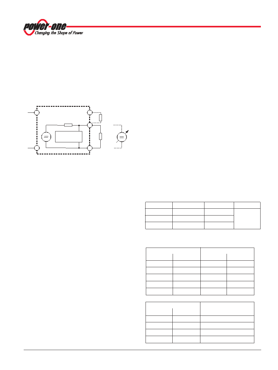
Adjustable Output Voltage
As a standard feature, the converters offer adjustable output
voltages by using the control input R. Fig. 10 shows the
schematic diagram of the circuitry. If the control input is left
open-circuit, the output voltage is set to Vo nom.
Note: For output voltages Vo > Vo nom, the minimum input voltage Vi min
(see Electrical Input Data) increases proportionally to Vo /Vo nom.
The R input is referenced to the secondary side of the
Fig. 10
Output voltage control by means of the R input
converter. Adjustment of the output voltage Vo (or Vo1) is
possible by means of either an external resistor or a voltage
source.
a) Adjustment by means of an external resistor Rext.
Depending upon the value of the required output voltage,
the resistor shall be connected:
either: Between the R pin and Vo– (or Vo1) to achieve an
output voltage adjustment range of Vo
≈ 80 to 100 % of
Vo nom.
Vo
Rext1
≈ 4 kΩ –––––––––
Vo nom – Vo
or: Between the R pin and Vo+ (or Vo1+) to achieve an
output voltage range of Vo
≈ 100 to 105% of Vo nom.
(Vo – 2.5V)
Rext2
≈ 4 kΩ ––––––––––––––––––
2.5 V (Vo/Vo nom – 1)
b) Adjustment by means of an external voltage Vext between
Vo– (or Vo1–) and the R pin.
The control voltage range is 1.96 to 2.62 V and allows for
adjustment in the range of Vo
≈ 80 to 105% of Vo nom.
Vo 2.5 V
Vext
≈ ––––––––
Vo nom
Note: Applying an external control voltage >2.75 V may damage the
converter.
Reference Output (Ref)
The converter provides a stable 5 V (± 0.25 V) reference signal
on pin 7 (Ref). The output is protected by a 1 k
Ω resistor.
Note: It is recommended to connect a filter capacitor (0.1 F)
between Ref and Vi–, if Ref is used.
Synchronization (W)
It is possible to synchronize the switching frequency of one or
more converters to an external clock signal. If this option is
required, consult Power-One for full application details.
Note: In case of no synchronization, pin 6 (W) can be connected to
Vi– (pin 2) or left open-circuit.
Shutdown (S
_
D
_
)
The outputs of the converters may be enabled or disabled by a
logic signal (TTL, CMOS, etc.) applied between the shutdown
pin 8 and Vi–. If the shutdown function is not required, pin 8
should be left open-circuit. Voltage on pin 8:
Converter operating:
2.0 to 20 V
Converter disabled:
– 0 .7 to +0.7 V
Progr. Input Undervoltage Lockout PUL
A special feature of these converters is the adjustable
accurate
undervoltage
lockout
function,
protecting
the
converter (and the system) from high currents caused by
operation at too low input voltage. This ensures easier startup
in distributed power systems.
The undervoltage lockout levels may be programmed by use
of an external resistor RPUL (between PUL and Vi–) to increase
the preset levels as indicated in the table below.
Table 8: Turn-on voltage (pin 1 left open-circuit)
Model
Trigger level
Hysteresis
Unit
24IMX70
12 to 13
V
40IMX70
19 to 20.5
110IMY70
44.5 to 47.5
typ. 6
Table 9: Typical values for RPUL and the respective turn-on
input voltage Vi LO.
24IMX70
40 IMX70
R PUL [k
Ω
Ω]
Vi LO [V]
R PUL [k
Ω
Ω]
Vi LO [V]
∞
≤ 12
∞
≤ 20
39
43
19
16
13
10
9.1
0
110 IMY70
R PUL [k
Ω
Ω]
Vi LO [V]
∞
46
270
50
110
57
82
61
R
Vo+
Vo–
+
Vext
–
4 kΩ
Vref = 2.5 V
Control
logic
Rext1
Rext2
06029d
Vi–
Vi+
相关PDF资料 |
PDF描述 |
|---|---|
| 48IMS7-05-9Z | 1-OUTPUT 6.1 W DC-DC REG PWR SUPPLY MODULE |
| 48IMS25-15-9 | 1-OUTPUT 24 W DC-DC REG PWR SUPPLY MODULE |
| 40IMX15-05-9RZ-G | 1-OUTPUT 12.8 W DC-DC REG PWR SUPPLY MODULE |
| 40IMX7-15-15-9C | 2-OUTPUT 7.2 W DC-DC REG PWR SUPPLY MODULE |
| 40IMX7-03-9 | 1-OUTPUT 5 W DC-DC REG PWR SUPPLY MODULE |
相关代理商/技术参数 |
参数描述 |
|---|---|
| 40IMX7-03-8 | 功能描述:DC/DC转换器 7W (3V) DC Input (16.8-75V) RoHS:否 制造商:Murata 产品: 输出功率: 输入电压范围:3.6 V to 5.5 V 输入电压(标称): 输出端数量:1 输出电压(通道 1):3.3 V 输出电流(通道 1):600 mA 输出电压(通道 2): 输出电流(通道 2): 安装风格:SMD/SMT 封装 / 箱体尺寸: |
| 40IMX7-03-8G | 功能描述:DC/DC转换器 RoHS:否 制造商:Murata 产品: 输出功率: 输入电压范围:3.6 V to 5.5 V 输入电压(标称): 输出端数量:1 输出电压(通道 1):3.3 V 输出电流(通道 1):600 mA 输出电压(通道 2): 输出电流(通道 2): 安装风格:SMD/SMT 封装 / 箱体尺寸: |
| 40IMX7-03-9 | 制造商:POWER-ONE 制造商全称:Power-One 功能描述:7 Watt DC-DC Converters |
| 40IMX7-05-05-8 | 功能描述:DC/DC转换器 7W (2x 5V) DC Input (16.8-75V) RoHS:否 制造商:Murata 产品: 输出功率: 输入电压范围:3.6 V to 5.5 V 输入电压(标称): 输出端数量:1 输出电压(通道 1):3.3 V 输出电流(通道 1):600 mA 输出电压(通道 2): 输出电流(通道 2): 安装风格:SMD/SMT 封装 / 箱体尺寸: |
| 40IMX7-05-05-8G | 功能描述:DC/DC转换器 RoHS:否 制造商:Murata 产品: 输出功率: 输入电压范围:3.6 V to 5.5 V 输入电压(标称): 输出端数量:1 输出电压(通道 1):3.3 V 输出电流(通道 1):600 mA 输出电压(通道 2): 输出电流(通道 2): 安装风格:SMD/SMT 封装 / 箱体尺寸: |
发布紧急采购,3分钟左右您将得到回复。