- 您现在的位置:买卖IC网 > PDF目录30629 > 4206K (Maxim Integrated Products, Inc.) 17- OUTPUT LED DRIVER/GPO PDF资料下载
参数资料
| 型号: | 4206K |
| 厂商: | Maxim Integrated Products, Inc. |
| 元件分类: | LED驱动器 |
| 英文描述: | 17- OUTPUT LED DRIVER/GPO |
| 中文描述: | 17 -输出LED驱动器/ GPO中 |
| 文件页数: | 12/23页 |
| 文件大小: | 724K |
| 代理商: | 4206K |
MAX6964
17-
LED
/GPO
2
_______________________________________________________________________________________
ABSOLUTE MAXIMUM RATINGS
Stresses beyond those listed under “Absolute Maximum Ratings” may cause permanent damage to the device. These are stress ratings only, and functional
operation of the device at these or any other conditions beyond those indicated in the operational sections of the specifications is not implied. Exposure to
absolute maximum rating conditions for extended periods may affect device reliability.
Voltage (with respect to GND)
V+ .............................................................................-0.3V to +4V
SCL, SDA, AD0, BLINK, RST ...................................-0.3V to +6V
O0–O16 ....................................................................-0.3V to +8V
DC Current on O0 to O16 ...................................................55mA
DC Current on SDA.............................................................10mA
Maximum GND Current ....................................................350mA
Continuous Power Dissipation (TA = +70°C)
24-Pin QSOP (derate 9.5mW/°C over +70°C)..............761mW
24-Pin QFN (derate 20.8mW/°C over +70°C) ............1666mW
Operating Temperature Range .........................-40°C to +125°C
Junction Temperature ......................................................+150°C
Storage Temperature Range .............................-65°C to +150°C
Lead Temperature (soldering, 10s) .................................+300°C
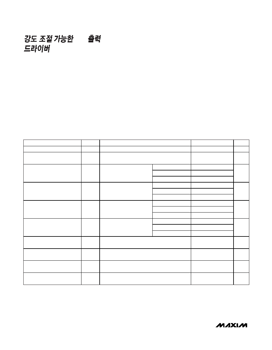
ELECTRICAL CHARACTERISTICS
(Typical Operating Circuit, V+ = 2V to 3.6V, TA = TMIN to TMAX, unless otherwise noted. Typical values are at V+ = 3.3V, TA = +25°C.)
(Note 1)
PARAMETER
SYMBOL
CONDITIONS
MIN
TYP
MAX
UNITS
Operating Supply Voltage
V+
2.0
3.6
V
Output Load External Supply
Voltage
VEXT
07
V
TA = +25°C
1.2
2.3
TA = -40°C to +85°C
2.6
Standby Current
(Interface Idle, PWM Disabled)
I+
SCL and SDA at V+; other
digital inputs at V+ or GND;
PWM intensity control disabled
TA = TMIN to TMAX
3.3
A
TA = +25°C
8.5
15.1
TA = -40°C to +85°C
16.5
Supply Current
(Interface Idle, PWM Enabled)
I+
SCL and SDA at V+; other
digital inputs at V+ or GND;
PWM intensity control disabled
TA = TMIN to TMAX
17.2
A
TA = +25°C
50
95.3
TA = -40°C to +85°C
99.2
Supply Current
(Interface Running, PWM
Disabled)
I+
fSCL = 400kHz; other digital
inputs at V+ or GND; PWM
intensity control enabled
TA = TMIN to TMAX
102.4
A
TA = +25°C
57
110.2
TA = -40°C to +85°C
117.4
Supply Current
(Interface Running, PWM
Enabled)
I+
fSCL = 400kHz; other digital
inputs at V+ or GND; PWM
intensity control enabled
TA = TMIN to TMAX
122.1
A
Input High Voltage
SDA, SCL, AD0, BLINK,
RST
VIH
0.7 x
V+
V
Input Low Voltage
SDA, SCL, AD0, BLINK,
RST
VIL
0.3 x
V+
V
Input Leakage Current
SDA, SCL, AD0, BLINK,
RST
IIH, IIL
0
≤ input voltage ≤ 5.5V
-0.2
+0.2
A
Input Capacitance
SDA, SCL, AD0, BLINK,
RST
8pF
相关PDF资料 |
PDF描述 |
|---|---|
| 420LB60 | TWO LINE PAIR 4-20mA CONTROL LOOP PROTECTOR |
| 420LE28 | TWO LINE PAIR 4-20mA CONTROL LOOP PROTECTOR |
| 420LE35 | TWO LINE PAIR 4-20mA CONTROL LOOP PROTECTOR |
| 420LE60 | TWO LINE PAIR 4-20mA CONTROL LOOP PROTECTOR |
| 4216800L | 3.3 V OPERATION 16 M-BIT DYNAMIC RAM 2 M-WORD BY 8-BIT, FAST PAGE MODE |
相关代理商/技术参数 |
参数描述 |
|---|---|
| 4206LBCT | 功能描述:折皱器 MOD PLG CRIMP TOOL RoHS:否 制造商:Hirose Connector 类型: 描述/功能:Cable and Shield Crimper |
| 4206PA51G01800 | 制造商:Laird Technologies Inc 功能描述:GASKET FABRIC/FOAM 10X457.2MM SQ |
| 4206PA51H01200 | 功能描述:GK NICU PTAFG PU V0 SQ 制造商:laird technologies emi 系列:- 零件状态:有效 形状:方形 厚度 - 总:0.395"(10.00mm) 宽度:0.395"(10.00mm) 长度:12.000"(304.80mm) 粘合剂:- 温度范围:- 标准包装:79 |
| 4206PA51H01800 | 功能描述:GASKET FABRC/FOAM 10X10MM SQUARE RoHS:是 类别:RF/IF 和 RFID >> RFI 和 EMI - 屏蔽和吸收材料 系列:* MSDS 材料安全数据表:AU 2190 MSDS 特色产品:Electromagnetic Compatible (EMC) Products 标准包装:1 系列:AU 形状:带 厚度 - 总计:0.004"(0.11mm) 宽:6.00"(152.40mm)1/2' 长度:1'(304.0mm)12" 胶合剂:丙烯酸,导电 温度范围:- 产品目录页面:549 (CN2011-ZH PDF) 其它名称:3M2190D-1FT |
| 4207 | 功能描述:保险丝夹 TRON FUSECLIP RoHS:否 制造商:Schurter 产品:Fuse Clips 类型:Fuse Clip 用于:ASO 10.3 x 38 mm |
发布紧急采购,3分钟左右您将得到回复。