- 您现在的位置:买卖IC网 > PDF目录248174 > 42H36-01-1-02S (GRAYHILL INC) ROTARY SWITCH-2POSITIONS, SPDT, LATCHED, 0.025A, 28VDC, PANEL MOUNT-THREADED PDF资料下载
参数资料
| 型号: | 42H36-01-1-02S |
| 厂商: | GRAYHILL INC |
| 元件分类: | 开关 |
| 英文描述: | ROTARY SWITCH-2POSITIONS, SPDT, LATCHED, 0.025A, 28VDC, PANEL MOUNT-THREADED |
| 封装: | ROHS COMPLIANT |
| 文件页数: | 8/10页 |
| 文件大小: | 1279K |
| 代理商: | 42H36-01-1-02S |
Grayhill, Inc. 561 Hillgrove Avenue LaGrange, Illinois
60525-5997 USA Phone: 708-354-1040 Fax: 708-354-2820 www.grayhill.com
Rotary
Switches
Multi-Deck Rotary Switches
MILITARY QUALIFIED
Single Shaft Switches
The military styles of the single shaft Series 42
and 44 rotary switches are qualified to MIL-DTL-
3786/4, specifically SR04-1. Qualification
includes two temperature ranges. Unsealed
styles M, MB, MG and MBG are qualified for -65
to 85°C. Unsealed styles H, HB, HG and HBG,
plus sealed styles HS, HBS, HGS and HBGS are
qualified for -65°C to 125°C. Qualification includes
low level switching and shaft grounding as
specified in MIL-DTL-3786. Qualification includes
30°, 36°, 45°, 60° and 90° angles of throw with
solder lug terminals. The military styles are
dimensionally the same as the standard styles
with two exceptions. The location of the common
for the 3-pole switch differs (see circuit diagrams)
and the non-turn tab for styles HS, HBS, HGS
and HBGS differs per the Shaft and Panel Seal
description following.
Two Switches, Concentric Shafts
The M style of the concentric shaft Series 43
and 54 switches is qualified to MIL-DTL-3786/4,
specifically SR04-2. Unsealed switches are
qualified for -65°C to 85°C in 30°, 36°, 45°, 60°
and 90° throws. The standard and military
styles of the concentric switches have the
same dimensions with the exception of the
location of the 3 pole common (see circuit
diagrams). The 30° and 36° throws are described
in the ordering information. If the 45°, 60° and
90° throws are required, they can be provided in
Section A of the Series 54 Rotary Switches; see
Standard Options, page J-9.
Add-A-Pot Switches
The military style of the add-a-pot Series 54
switch is qualified to MIL-DTL-3786/4, specifically
SR04-3. These unsealed switches are qualified
for -65°C to 85°C in 30°, 45°, 60° and 90° throws.
The dimensions of the military style add-a-pot
switches are not the same as the standard add-
a-pot switches; see drawings.
All Qualified Switches
Complete electrical ratings and characteristics
for all of these qualified switches are listed on the
following pages. Standard variations such as
terminals, shaft and/or bushing length etc., which
do not affect performance, can be marked as
qualified product. Adjustable stops cannot be
qualified. Contact Grayhill for details about
variations.
Military qualified switches may be ordered by
the military M number listed in MIL-DTL-3786/4
or by the Grayhill part number. They will be
marked to specifications.
MILITARY QUALIFIED SHAFT AND
PANEL SEAL:
Styles HS, HBS, HGS and HBGS
The shaft is sealed to the bushing by an internal
O-ring per MIL-P-5516B. The bushing is sealed
to the panel with a silicone rubber washer and a
stainless steel backing washer. The combined
uncompressed thickness is 0.055" (1,40). Since
this switch has a flat cover, a non-turn washer is
supplied (see Panel Seal Kit). If using it, mount
it in front of the panel.
SPECIFICATIONS:
Electrical Ratings
Standard Style
Rated: To make and break the following
loads:
Angle of Throw
30° or 36°
45° or 60°
90°
115 Vac resistive
1 amp
5 amps
6-28 Vdc resistive
1 amp
2 amps
115 Vac inductive
0.25 amp
2 amps
115 Vdc inductive
0.02 amp
—
6-28 Vdc inductive
0.10 amp
—
115 Vdc resistive
0.10 amp
—
To carry 10 amps continuously.
Contact Resistance: 50 milliohms maximum
Insulation Resistance: 1,000 megaohms
minimum
Voltage Breakdown: 1,000 Vac initially (500
Vac or better after most environmental tests)
Life Expectancy: 100,000 mechanical cycles
of operation.
Note: Actual life is determined
by a number of factors, including electrical
loading, rate of rotation and environment, as
well as maximum voltage breakdown required
at the end of life.
UL Recognition–
Styles UA, UD, UM, UP, US and USP
Grayhill styles A and M and their variations
(D, P, S and SP) of the Series 42, 43, 44 and
54 rotary switches have been tested by
Underwriters Laboratories. The letter U in the
style indicates proper marking as required by
Underwriters Laboratories. These switches
are recognized under file number E35289.
The UL rating for the Series 42, 43, 44 and 54
is as follows:
Electrical Parameters: style UA = 1.0 ampere
at 125 Vac. Style UM = 1.0 ampere at 125 Vac
and also .5 ampere at 125 Vac, inductive
load, 0.75 to 0.8 power factor.
Rating based on the following criteria:
Overload: 50 operations at 150% rated AC
load
Endurance: 6000 operations at the rated load
with 1000 Vac dielectric strength before and
after test
Temperature Rise: Not to exceed 30°C when
carrying rated AC load after test.
Note: all dimensional drawings for the standard
style Series 42, 43, 44 and 54 also apply to
these switches, with the exception that switches
are marked per specifications.
Electrical Ratings
Military Style
General Rating: This rating is based on
standard Grayhill tests of the Military style
switch done at ambient conditions. It is provided
for comparison to the Standard Style switch.
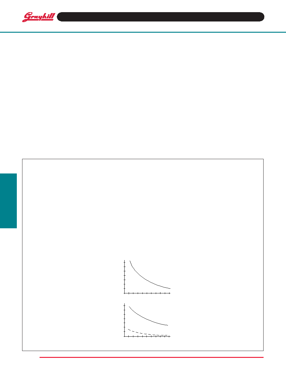
Charts shown for non-shorting contacts (break
7
6
5
4
3
2
1
0
CYCLES x 1,000
10
25
50
CURRENT
(AMPS)
VOLTAGE 115 VAC
RESISTIVE
CYCLES x 1,000
010
25
50
1.7
1.5
1.2
1.0
.75
.50
.20
0
CURRENT
(AMPS)
VOLTAGE 30 VDC
RESISTIVE
INDUCTIVE
(2.8 HENRIES)
before make)
Voltage and Load: As listed in the chart
One cycle is 360° rotation and a return
through all switch positions to the starting
position. The data for the curves was
measured at sea level, 25°C and 68% relative
humidity.
The Series 42, 43, 44 and 54, style M, H and
HS switches are made to meet requirements
of MIL-DTL-3786, style SR04. Diallyl phthalate
molded parts and the design of internal
switching elements provide exceptional
performance.
Curves shown are typical load-life curves for
Series 42, 43, 44 and 54, style M, H and HS
switches with 30° or 36° angles of throw.
They show the numbers of cycles of rotational
life expectancy for the types of loads shown.
Thus, with a 5 amp, 115 Vac resistive load,
10,000 cycles of life is expected. If the load
is reduced to 3 amps, life is increased to
25,000 cycles. The larger angles of throw
(45°, 60° or 90°) switch larger currents for a
like number of cycles.
Life limiting or failure criteria for these curves
are:
Contact Resistance: 50 milliohms maximum
Insulation Resistance: 1,000 megaohms
minimum between mutually insulated parts
Voltage Breakdown: 1,000 Vac minimum
between mutually insulated parts. These
switches will carry 10 amps with maximum
contact temperature rise of 20°C. Life can be
predicted by Grayhill if less critical life
characteristics, elevated temperature or
reduced pressure is involved.
Rotary
28
相关PDF资料 |
PDF描述 |
|---|---|
| 42HS36-01-1-10S | ROTARY SWITCH-10POSITIONS, SP10T, LATCHED, PANEL MOUNT-THREADED |
| 42HS36-01-2-02N | ROTARY SWITCH-2POSITIONS, DPDT, LATCHED, 0.025A, 28VDC, PANEL MOUNT-THREADED |
| 44MG30-01-4-02S | ROTARY SWITCH-2POSITIONS, 4PDT, LATCHED, 0.025A, 28VDC, PANEL MOUNT-THREADED |
| 44HBS45-01-2-04S | ROTARY SWITCH-4POSITIONS, DP4T, LATCHED, 0.025A, 28VDC, PANEL MOUNT-THREADED |
| 44MG45-12-1-08N-F | ROTARY SWITCH-8POSITIONS, SP8T, LATCHED, 0.025A, 28VDC, PANEL MOUNT-THREADED |
相关代理商/技术参数 |
参数描述 |
|---|---|
| 42H36-01-1-03N | 制造商:Grayhill 功能描述:SWIT ROTARY SP 3 SHAFT SLDR LUG 115VAC 30VDC - Bulk 制造商:Grayhill 功能描述:Switch Rotary SP3T 3 Flatted Shaft Solder Lug 1A 115VAC 115VDC |
| 42H36-01-1-03S | 制造商:Grayhill 功能描述:- Bulk 制造商:Grayhill 功能描述:Switch Rotary SP3T 3 Flatted Shaft Solder Lug 1A 115VAC 115VDC |
| 42H36-01-1-04N | 制造商:Grayhill 功能描述:SWIT ROTARY SP 4 SHAFT SLDR LUG 115VAC 30VDC - Bulk 制造商:Grayhill 功能描述:Switch Rotary SP4T 4 Flatted Shaft Solder Lug 1A 115VAC 115VDC |
| 42H36-01-1-04S | 功能描述:SWITCH ROTARY 36 DEG 1 DECK, 1 P 制造商:grayhill inc. 系列:* 零件状态:在售 标准包装:1 |
| 42H36-01-1-05N | 制造商:Grayhill 功能描述:SWIT ROTARY SP 5 SHAFT SLDR LUG 115VAC 30VDC - Bulk 制造商:Grayhill 功能描述:Switch Rotary SP5T 5 Flatted Shaft Solder Lug 1A 115VAC 115VDC |
发布紧急采购,3分钟左右您将得到回复。