参数资料
| 型号: | 4804S REV D-G |
| 厂商: | Aavid Thermalloy |
| 文件页数: | 13/116页 |
| 文件大小: | 0K |
| 描述: | MOUNTING KIT |
| 标准包装: | 1,000 |
| 附件类型: | 安装套件 |
| 适用于相关产品: | TO-3 |
| 其它名称: | 035000 |
第1页第2页第3页第4页第5页第6页第7页第8页第9页第10页第11页第12页当前第13页第14页第15页第16页第17页第18页第19页第20页第21页第22页第23页第24页第25页第26页第27页第28页第29页第30页第31页第32页第33页第34页第35页第36页第37页第38页第39页第40页第41页第42页第43页第44页第45页第46页第47页第48页第49页第50页第51页第52页第53页第54页第55页第56页第57页第58页第59页第60页第61页第62页第63页第64页第65页第66页第67页第68页第69页第70页第71页第72页第73页第74页第75页第76页第77页第78页第79页第80页第81页第82页第83页第84页第85页第86页第87页第88页第89页第90页第91页第92页第93页第94页第95页第96页第97页第98页第99页第100页第101页第102页第103页第104页第105页第106页第107页第108页第109页第110页第111页第112页第113页第114页第115页第116页
11
READING
A
T
HERMAL
PERFORMANCE
GR
APH
EUROPE
ASIA
Italy Tel: +39 051 764011 email: sales.it@aavid.com
United Kingdom Tel: +44 1793 401400 email: sales.uk@aavid.com
Singapore Tel: +65 6362 8388 email: sales@aavid.com.sg
Taiwan Tel: +886(2) 2698-9888 email: sales@aavid.com.tw
AMERICA
USA Tel: +1 (603) 224-9988 email: info@aavid.com
www.aavidthermalloy.com
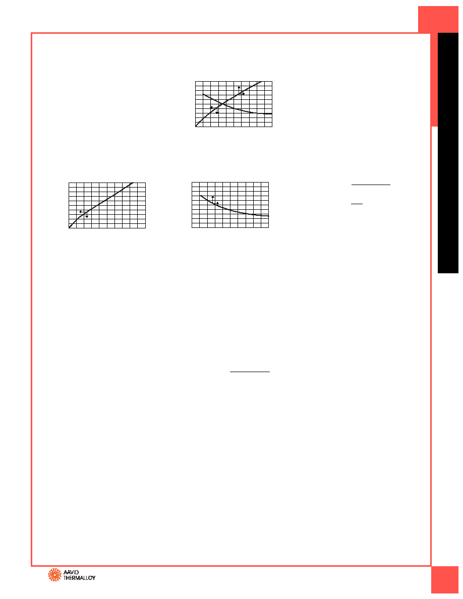
The performance graphs you will see in this
catalog (see graph 579802) are actually a
composite of two separate graphs which
have been combined to save space. The small
arrows on each curve indicate to which axis
the curve corresponds. Thermal graphs are
published assuming the device to be cooled
is properly mounted and the heat sink is in
its recommended mounting position.
GRAPH A is used to show heat sink perform-
ance when used in a natural convection envi-
ronment (i.e. without forced air). This graph
starts in the lower left hand corner with the
horizontal axis representing the heat dissipa-
tion (watts) and the vertical left hand axis
representing the rise in heat sink mounting
surface temperature above ambient (°C). By
knowing the power to be dissipated, the
temperature rise of the mounting surface
can be predicted. Thermal resistance in natu-
ral convection is determined by dividing this
temperature rise by the power input (°C/W).
EXAMPLE A: Aavid Thermalloy part number
579802 is to be used to dissipate 3 watts of
power in natural convection. Because we are
dealing with natural convection, we refer to
graph “A”. Knowing that 3 watts are to be dis-
sipated, follow the grid line to the curve and
find that at 3 watts there is a temperature
rise of 75°C. To get the thermal resistance,
divide the temperature rise by the power
dissipated, which yields 25°C/W.
GRAPH B is used to show heat sink per-
formance when used in a forced convec-
tion environment (i.e. with forced air flow
through the heat sink). This graph has its
origin in the top right hand corner with
the horizontal axis representing air velocity
over the heat sink LFM* and the vertical
axis representing the thermal resistance of
the heat sink (°C/W). Air velocity is calculat-
ed by dividing the output volumetric flow
rate of the fan by the cross-sectional area
of the outflow air passage.
EXAMPLE B: For the same application
we add a fan which blows air over the heat
sink at a velocity of 400 LFM.
The addition of a fan indicates the use of
forced convection and therefore we refer
to graph “B”. This resistance of 9.50°C/W is
then multiplied by the power to be dissi-
pated, 3 watts. This yields a temperature
rise of 28.5°C.
CONVERTING VOLUME
TO VELOCITY
Although most fans are normally rated and
compared at their free air delivery at zero
back pressure, this is rarely the case in most
applications. For accuracy, the volume of
output must be derated 60%–80% for
the anticipation of back pressure.
EXAMPLE: The output air volume
of a fan is given as 80 CFM. The output area
is 6 inches by 6 inches or 36 in2 or 25 ft2.
To find velocity:
80
0.25
Velocity is 320 LFM, which at 80%,
derates to 256 LFM.
DESIGN ASSISTANCE
Aavid Thermalloy can assist in the design
of heat sinks for both forced and natural
convection applications. Contact us for help
with your next thermal challenge. For more
information, visit our web site at:
www.aavidthermalloy.com
Heat Dissipated—Watts
0
20
40
60
80
100
01
2
3
4
5
Mounting
Surface
Temp
Rise
Above
Ambient—
°
C
Air Velocity—Feet Per Minute
Thermal
Resistance
From
MTG
Surface
to
Ambient—
°
C/Watt
20
16
12
4
8
0
400
200
600
800
1000
GRAPH B
Velocity (LFM) =
Velocity =
= 320
Air Velocity—Feet Per Minute
Heat Dissipated—Watts
Thermal
Resistance
From
MTG
Surface
to
Ambient—
°
C/Watt
20
0
20
40
60
80
100
01
2
3
4
5
16
12
4
8
0
400
200
600
800
1000
Mounting
Surface
Temp
Rise
Above
Ambient—
°
C
GRAPH A
579802
Reading a Thermal Performance Graph
Velocity
(LFM)* = Volume (CFM)**
area (ft2)
* Linear feet per minute
** Cubic feet per minute
Volume (CFM)
area (ft2)
相关PDF资料 |
PDF描述 |
|---|---|
| 4-641218-5 | 15P MTA156 CONN ASSY 20AWG LF |
| RAVF164DFT3K30 | RES ARRAY 3.3K OHM 4 RES 1206 |
| 0395238520 | 5MM EURO PLUG STR GRN AU 20POS |
| 0395237520 | 5MM EURO PLUG STR GRN AU 20POS |
| 4-641217-5 | 15P MTA156 CONN ASSY 18AWG ORA |
相关代理商/技术参数 |
参数描述 |
|---|---|
| 4804UCC | 制造商:未知厂家 制造商全称:未知厂家 功能描述:x4 SRAM |
| 4804UCP | 制造商:未知厂家 制造商全称:未知厂家 功能描述:x4 SRAM |
| 4805 | 功能描述:支架与垫片 .875 NYL stdoff 4-40 Thread RoHS:否 制造商:Schurter 类型:Transipillar Spacers 长度:16 m 螺纹大小:M4 外径:10 mm 材料:Nylon with Steel 电镀:Zinc |
| 4805/POM | 功能描述:RF 连接器 SMA FOR RG174 RoHS:否 制造商:Bomar Interconnect 产品:Connectors 射频系列:BNC 型式:Jack (Female) 极性: 触点电镀:Gold 阻抗: 端接类型:Solder 主体类型:Straight Bulkhead 电缆类型: |
| 48050 | 功能描述:TWEEZER SELF CLOSE FLAT SQ R50SA RoHS:否 类别:工具 >> 镊子 系列:- 标准包装:1 系列:- 特点:每组 3 个,防静电 端头 - 样式:多重 尖端 - 类型:2个精细型,1个圆头 尖端 - 形状:多重 长度 - 总体:4.72"(120mm) 维持尺寸:- 样式编号:- 材质:塑料手柄,陶瓷端头 其它名称:243-1078 |
发布紧急采购,3分钟左右您将得到回复。