- 您现在的位置:买卖IC网 > PDF目录156695 > 504M06QE100 (ITW PAKTRON) RC NETWORK, BUSSED, 0.5W, 100ohm, 600V, 0.5uF, THROUGH HOLE MOUNT, 2 PDF资料下载
参数资料
| 型号: | 504M06QE100 |
| 厂商: | ITW PAKTRON |
| 元件分类: | 电阻 |
| 英文描述: | RC NETWORK, BUSSED, 0.5W, 100ohm, 600V, 0.5uF, THROUGH HOLE MOUNT, 2 |
| 封装: | RADIAL LEADED, ROHS COMPLIANT |
| 文件页数: | 2/2页 |
| 文件大小: | 181K |
| 代理商: | 504M06QE100 |
Type Q/QRL QuencharcCapacitor
RC Snubber Network
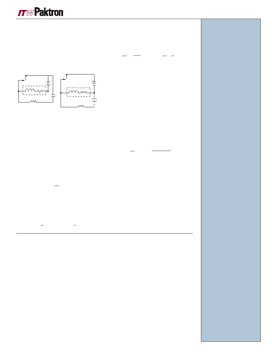
The most popular and commonly used method of
arc suppression is to connect a resistor-capacitor
network as shown in Figures A and B. The
preferred method of connection is across the
contacts it wants to protect. However, the network
can be hooked across the load, as is shown by the
dashed line, when all inductance of the load circuit
is considered lumped together.
When the contacts
open, the voltage across the uncharged capacitor is
zero and the transient voltage starts charging the
capacitor. In the meantime, the gap of the contact is
steadily widened, and by the time the capacitor is
charged to its full potential, the contact gap is
widened well beyond the minimum breakdown
potential of air, thus preventing the arcing.When the
contact closes, the inrush current from the capacitor
may damage the contact, and here resistance is
needed to limit the maximum current to Eo/Rc
during the contact closure.
The induced voltage on opening the
contact is
and, as can be seen, the larger the value of a series
resistor, the higher the induced voltage. On the
other hand, the lower series resistance makes the
current on contact closure higher. The time
dependence of the voltage is given by:
and the rate of voltage change, which is important
in transient suppression of triac switching, is:
Equation (3) tells us that by knowing the circuit
conditions with given values of L and coil resistance
that limit the current prior to contact opening, the
rate of voltage rise is inversely proportional to
capacitance. In other words, the larger the
capacitance, the greater is the transient
suppression. However, when the contact closes,
the additional energy stored in the capacitor has to
be discharged through the contact. Hence, a
compromise has to be made in the selection of
both resistance and capacitance.
In an effort to provide a simple answer to
designers’ requests for proper values of resistance
and capacitance, some relay manufacturers came
out with empirical formulas and nomographs. For
instance, C.C. Bates1 gives the equations
where
C = capacitance in mF
I = load current in amperes prior to contact
opening
R = resistance in ohms in series with capacitor
Eo = source voltage
The choice of resistance and capacitance value
however, is quite flexible. In fact, the choice is so
simple that one does not need a nomograph at all.
Besides, a nomograph published by a certain relay
manufacturer may be for the particular relays the
firm manufactures, not necessarily universal.
1Bates, C.C., “Contact Protection of
Electromagnetic Relays.” Electro-mechanical
Design, August, 1966.
Eo
C
L
RL
RC
Eo
C
L
RL
RC
V = IRC = RC Eo
(1)
RL
Figure A
Figure B
dv = L d
2i + (RL + RC) di + i
dt
dt2
dt C
C = I
2
R =
Eo
10
10I(1+ 50 )
Eo
HOW QUENCHARC
WORKS
CHOOSING A QUENCHARC
In choosing a Quencharc, first of all, check
the maximum switching current rating of the
contacts to be protected. This value differs for
different types of contact materials and
different types of relays. The maximum
current during the contact closure with an RC
network is Eo/Rc, where Eo is the source
voltage and Rc is the resistance value of the
network. The quantity Eo/Rc must be lower
than the maximum switching current for
obvious reasons. Next, the selection of
capacitance is best done with an oscilloscope.
Connect the oscilloscope probe to the relay
wiper and ground the other plate of the contact.
Without an RC network across the contacts,
check the amplitude of the transient voltage on
contact break and the amplitude of the current
on contact make. If the voltage is less than
300V and the current less than the maximum
switching current rating of the relay, and if you
don’t see any arcing, you may not need the
contact protection at all. If you spot arcing,
connect a .1 mF + 100 ohm, 250 VAC, QC100
(our most widely used Quencharc), across
the contacts, and observe the levels of
suppression, voltage on break and current on
make. The suppressed voltage should be
below 250V, which provides 70 volts of safety
margin from the breakdown potential of air. If
the voltage is still above 250V, try a .25 mF +
220 ohms or a .5 mF + 330 ohms range. If you
need a higher capacitance than 1.0 mF, you
may be better off with a Zener or a varistor in
terms of cost and space. For most relays and
triacs .1 mF + 100 ohms provides a satisfactory
suppression.
When protecting contacts in AC circuits, the
same general guidelines as for DC circuits can
be used, but the wattage of the resistor must
be considered if current flow is sustained for a
long enough period of time to heat the
component. Compute the impedance of the
RC unit to obtain a current value, then use I2R
and time considerations to determine whether
the standard network resistor is adequate.
oPERATINg
TEMPERATURE RANGE
–55°C to +85°C at full rated
voltage.
DISSIPATION FACTOR
The nominal dissipation factor
is determined from the
following equation:
DF = 2fCR + .006
where:
f = test frequency in hertz
C = nominal capacitance
value in farads
R = nominal value of series
resistor in ohms.
DIELECTRIC WITHSTANDING
VOLTAGE
Unit shall withstand a DC
potential of 1.6 times the DC
voltage rating. Testing con-
ducted at 25°C.
DC LIFE TEST
Unit shall withstand a test
potential of 125% of the rated
voltage for a period of 500
hours at a temperature of
85°C. A failure shall consist of:
Capacitance change greater
than 5%.
Dissipation factor greater than
original limits.
LONG TERM STABILITY
The capacitance shall not
change more than 2% when
stored at ambient temperature
and humidity for a period of 2
years or less.
PhySICAL
TOLERANCE
Capacitor ± 20%, Resistor
± 10%.
CONSTRUCTION*
Metallized polyester
capacitor in series with a
carbon composition resistor.
CASE
Coated with a UL94V-0
flame retardant epoxy.
WIRE LEADS
#20 AWG (.032") capacitor
end. #18 AWG (.040") for
QH & QV styles. Resistor
end .025" to 0.045".
MARkING
ITW, Quencharc,
capacitance, resistance,
voltage.
* 39 ohm resistors are power
wire-wound
V(t) = L di + (RL +RC
)i + Eo + 1 *
t idt
dt
C °
ITW Paktron P.O. Box 4539, 1205 McConville Road, Lynchburg, Virginia 24502 Tel 434-239-6941 Fax 434-239-4730 www.paktron.com
PAGE 19
相关PDF资料 |
PDF描述 |
|---|---|
| 504M02QA47 | RC NETWORK, BUSSED, 0.5W, 47ohm, 200V, 0.5uF, THROUGH HOLE MOUNT, 2 |
| 504M02QA22 | RC NETWORK, BUSSED, 0.5W, 22ohm, 200V, 0.5uF, THROUGH HOLE MOUNT, 2 |
| 504M02QA220 | RC NETWORK, BUSSED, 0.5W, 220ohm, 200V, 0.5uF, THROUGH HOLE MOUNT, 2 |
| 504M02QA100 | RC NETWORK, BUSSED, 0.5W, 100ohm, 200V, 0.5uF, THROUGH HOLE MOUNT, 2 |
| 505-5513 | PULSE TRANSFORMER FOR THYRISTOR TRIGGER; MOSFET GATE DRIVE APPLICATION(S) |
相关代理商/技术参数 |
参数描述 |
|---|---|
| 504M06QE150 | 功能描述:电磁干扰滤波器 0.5uF 250V 150 Ohms Quencharc RoHS:否 制造商:Cornell Dubilier 电容:0.5 uF 电路类型: 最大直流电流: 最大直流电阻: 电压额定值:600 V 容差:10 % 端接类型:Radial 工作温度范围:- 55 C to + 85 C 系列:Q/QRL |
| 504M06QE22 | 功能描述:电磁干扰滤波器 0.5uF 250V 22 Ohms Quencharc RoHS:否 制造商:Cornell Dubilier 电容:0.5 uF 电路类型: 最大直流电流: 最大直流电阻: 电压额定值:600 V 容差:10 % 端接类型:Radial 工作温度范围:- 55 C to + 85 C 系列:Q/QRL |
| 504M06QE47 | 功能描述:电磁干扰滤波器 0.5uF 250V 47 Ohms Quencharc RoHS:否 制造商:Cornell Dubilier 电容:0.5 uF 电路类型: 最大直流电流: 最大直流电阻: 电压额定值:600 V 容差:10 % 端接类型:Radial 工作温度范围:- 55 C to + 85 C 系列:Q/QRL |
| 504MAA-ABAF | 功能描述:32kHz ~ 80MHz LVCMOS CMEMS? Programmable Oscillator Surface Mount 1.7 V ~ 3.6 V 8.9mA Enable/Disable 制造商:silicon labs 系列:CMEMS? Si504 包装:托盘 零件状态:过期 类型:CMEMS? 可编程类型:由 Digi-Key 编程(请在网站订购单中输入您需要的频率) 可用频率范围:32kHz ~ 80MHz 功能:启用/禁用 输出:LVCMOS 电压 - 电源:1.7 V ~ 3.6 V 频率稳定度:- 频率稳定性(总体):±50ppm 工作温度:-20°C ~ 70°C 扩频带宽:- 电流 - 电源(最大值):8.9mA 等级:- 安装类型:表面贴装 封装/外壳:4-SMD,无引线(DFN,LCC) 大小/尺寸:0.157" 长 x 0.126" 宽(4.00mm x 3.20mm) 高度:0.035"(0.90mm) 电流 - 电源(禁用)(最大值):1μA 标准包装:1 |
| 504MAA-ABAG | 功能描述:32kHz ~ 80MHz LVCMOS CMEMS? Programmable Oscillator Surface Mount 1.7 V ~ 3.6 V 8.9mA Enable/Disable 制造商:silicon labs 系列:CMEMS? Si504 包装:托盘 零件状态:过期 类型:CMEMS? 可编程类型:由 Digi-Key 编程(请在网站订购单中输入您需要的频率) 可用频率范围:32kHz ~ 80MHz 功能:启用/禁用 输出:LVCMOS 电压 - 电源:1.7 V ~ 3.6 V 频率稳定度:- 频率稳定性(总体):±50ppm 工作温度:-40°C ~ 85°C 扩频带宽:- 电流 - 电源(最大值):8.9mA 等级:- 安装类型:表面贴装 封装/外壳:4-SMD,无引线(DFN,LCC) 大小/尺寸:0.157" 长 x 0.126" 宽(4.00mm x 3.20mm) 高度:0.035"(0.90mm) 电流 - 电源(禁用)(最大值):1μA 标准包装:1 |
发布紧急采购,3分钟左右您将得到回复。