- 您现在的位置:买卖IC网 > PDF目录156848 > 514NCAXXXXXXBAG (SILICON LABORATORIES) 250 MHz, OTHER CLOCK GENERATOR, PDSO6 PDF资料下载
参数资料
| 型号: | 514NCAXXXXXXBAG |
| 厂商: | SILICON LABORATORIES |
| 元件分类: | 时钟产生/分配 |
| 英文描述: | 250 MHz, OTHER CLOCK GENERATOR, PDSO6 |
| 封装: | 3.20 X 5 MM, ROHS COMPLIANT PACKAGE-6 |
| 文件页数: | 2/32页 |
| 文件大小: | 267K |
| 代理商: | 514NCAXXXXXXBAG |
第1页当前第2页第3页第4页第5页第6页第7页第8页第9页第10页第11页第12页第13页第14页第15页第16页第17页第18页第19页第20页第21页第22页第23页第24页第25页第26页第27页第28页第29页第30页第31页第32页
Si514
10
Preliminary Rev. 0.9
LP2 values, in addition to updating the value of M, which requires the VCO to be recalibrated. Refer to section
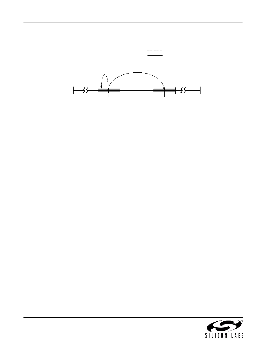
"2.3. Programming a Large Frequency Change (> ±1000 ppm)" on page 11. Figure 2 provides a graphic
depiction of the difference between small and large frequency changes.
Figure 2. Small vs Large Frequency Change Illustration
2.2. Programming a Small Frequency Change (sub ±1000 ppm)
The value of the feedback multiplier, M is the only parameter that needs to be updated for output frequency
changes less than ±1000 ppm from the center frequency (recalibrating the VCO is NOT required). This enables
the output to remain continuous during the change. For example, the output frequency can be swept continuously
between 148.5 MHz and 148.352 MHz (i.e., –0.997 ppm) with no output discontinuities or glitches by changing M
in either multiple steps or in a single step. For small frequency changes, each update of M requires 100 s to settle.
Note:
It is not possible to implement a frequency change ≥ ±1000 ppm using multiple small frequency changes
without changing the center frequency and recalibrating the VCO.
Use the following procedure to make small frequency changes:
1. If the current value of M is already known, then skip to step 2; else, using the serial port, read the current M
value (Registers 5-9).
2. Calculate the new value of M as follows (all values are in decimal format):
a. Mcurrent = M_Int + M_Frac/229 (Eq 2.2)
b. Mnew = Mcurrent x Fout_new / Fout_current (Eq 2.3)
c. M_Intnew = INT[Mnew]*
(Eq 2.4)
d. M_Fracnew = (Mnew – INT[Mnew]) x 229
(Eq 2.5)
*Where INT[n] rounds n down to the nearest integer (e.g., INT[3.9] = 3)
3. Using the I2C port, write the new value of M_Frac[23:0] (Not all registers need to be updated.)
(Registers: 5, 6, 7)
4. If necessary, write new value of M_Int[2:0] and M_Frac[28:24] register. (Register 8)
5. Write M_Int[8:3]. (Register 9) Frequency changes take effect when M_Int[8:3] is written.
Example 2.1:
An Si514 generating a 148.5 MHz clock must be reconfigured “on-the-fly” to generate a 148.352 MHz clock. This
represents a change of –0.996.633 ppm which is within the ±1000 ppm window.
1. Read the current value of M:
a. Register 5 = 0xD3 (M_Frac[7:0])
b. Register 6 = 0x65 (M_Frac[15:8])
c. Register 7 = 0x7C (M_Frac[23:16])
d. Register 8 = 0x49 (M_Int[2:0],M_Frac[28:24])
FVCO_MIN
(2080 MHz)
FVCO_MAX
(2500 MHz)
Range of small
frequency change
Programming a new center frequency requires a VCO
calibration and the output should be squelched
FCENTER
F'CENTER
Small Frequency Change
Large Frequency Change
FCENTER
+1000 ppm
FCENTER
-1000 ppm
相关PDF资料 |
PDF描述 |
|---|---|
| 514NCBXXXXXXAAGR | 170 MHz, OTHER CLOCK GENERATOR, PDSO6 |
| 514NCBXXXXXXAAG | 170 MHz, OTHER CLOCK GENERATOR, PDSO6 |
| 514NCCXXXXXXBAGR | 125 MHz, OTHER CLOCK GENERATOR, PDSO6 |
| 514PAAXXXXXXAAGR | 250 MHz, OTHER CLOCK GENERATOR, PDSO6 |
| 514PAAXXXXXXBAGR | 250 MHz, OTHER CLOCK GENERATOR, PDSO6 |
相关代理商/技术参数 |
参数描述 |
|---|---|
| 514NCC000980AAG | 功能描述:可编程振荡器 PROGRMABLE XO 6 PIN 0.7PS RS JTR RoHS:否 制造商:IDT 封装 / 箱体:5 mm x 7 mm x 1.5 mm 频率:15.476 MHz to 866.67, 975 MHz to 1300 MHz 频率稳定性:+/- 50 PPM 电源电压:3.63 V 负载电容:10 pF 端接类型:SMD/SMT 输出格式:LVPECL 最小工作温度:- 40 C 最大工作温度:+ 85 C 尺寸:7 mm W x 5 mm L x 1.5 mm H 封装: |
| 514P103212P | 制造商: 功能描述: 制造商:80205 功能描述: |
| 514P1032-12P | 制造商: 功能描述: 制造商:undefined 功能描述: |
| 514P1032-14P | 制造商: 功能描述: 制造商:undefined 功能描述: |
| 514P1032-8 | 制造商: 功能描述: 制造商:undefined 功能描述: |
发布紧急采购,3分钟左右您将得到回复。