- 您现在的位置:买卖IC网 > PDF目录63239 > 540/MK218 COMPARATOR, 10000 uV OFFSET-MAX, 1000 ns RESPONSE TIME, PDIP10 PDF资料下载
参数资料
| 型号: | 540/MK218 |
| 元件分类: | 比较器 |
| 英文描述: | COMPARATOR, 10000 uV OFFSET-MAX, 1000 ns RESPONSE TIME, PDIP10 |
| 封装: | DIP-16 |
| 文件页数: | 4/7页 |
| 文件大小: | 319K |
| 代理商: | 540/MK218 |
A
4
CALEX
FaxFACTS:
323
1997
Model 540 Voltsensor
http://www.calex.com
2401 Stanwell Drive
Concord, CA 94520-4841
(925) 687-4411 Fax (925) 687-3333
Applications
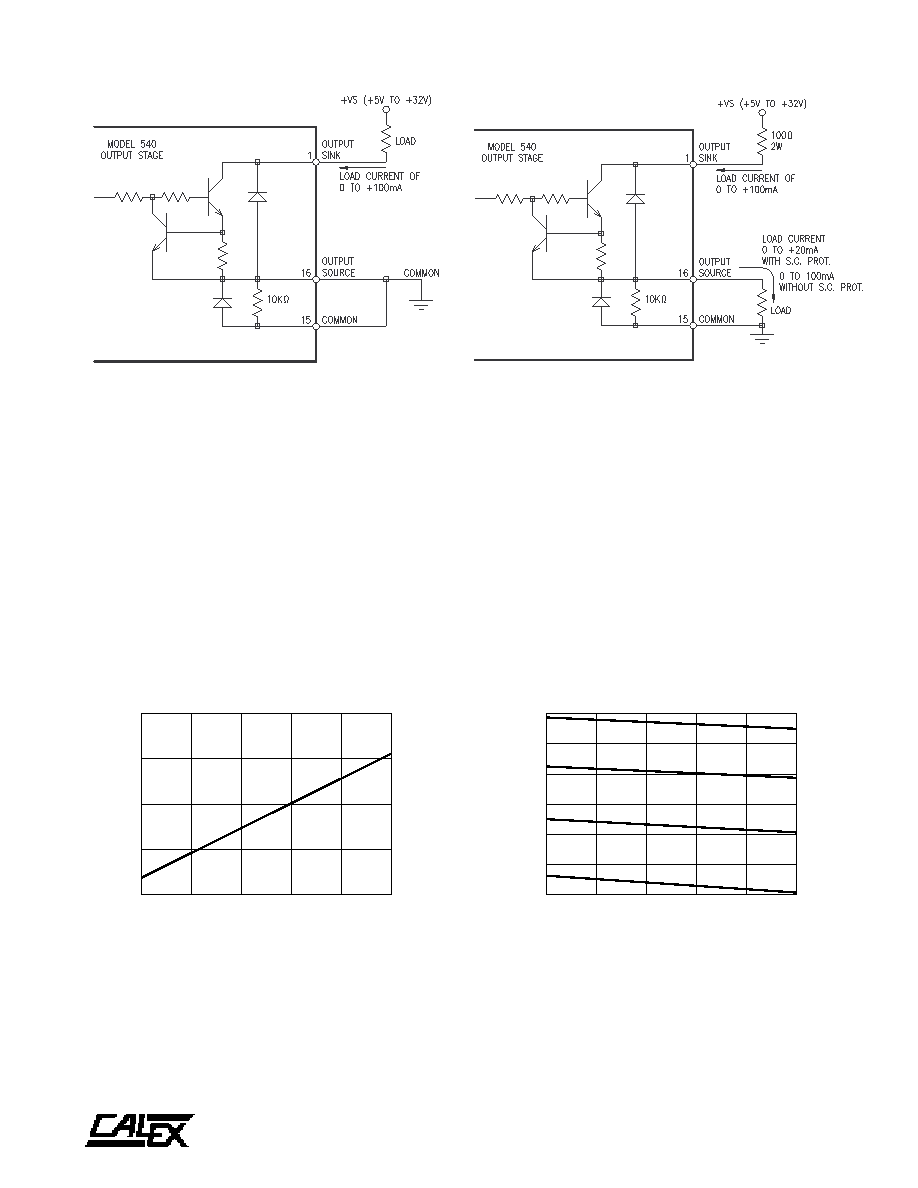
FIGURE 6. Model 540 Connected For Current-Sourcing Mode
Figure 6 shows the connections for current-source operation.
In this mode the Model 540 is short-circuit protected for +VS
of +5V to +15V. If short-circuit and current limiting protection
is desired for +VS of +16V to +32V, a 100
2W resistor should
be connected between +Vs and pin 1. Output voltage in the
current-source mode is +V
S - (3.5V + 10
I
L). Figure 7 is a
graph of output voltage versus load current for current source
operation. Output leakage does not exceed 1 mA.
FIGURE 4. Model 540 Connected For Current-Sinking Mode
The connections for current-sinking operation are shown
above in Figure 4. In this mode the Model 540 is short-circuit
protected and current-limited at 140 mA. The diode across
the output transistor protects the transistor against possible
back bias. Of the two output modes, current-sinking is more
desirable because there is less power dissipation in the low
output state. When the voltage at the NON INVERTING input
is more positive than the voltage at the INVERTING input, the
IC comparator switches to the high logic state. This causes
the output transistor to saturate, which will then energize the
load. Figure 5 is a graph of output voltage versus load current
for the saturated output transistor. Output leakage does not
exceed 1 mA.
0
2040
6080
100
LOAD CURRENT (mA)
0.00
0.20
0.40
0.60
0.80
Vo(SAT)
(VDC)
OUTPUT VOLTAGE FOR CURRENT-SINKING MODE
(LOW Logic State)
0
2040
6080
100
LOAD CURRENT (mA)
0
5
10
15
20
25
30
OUTPUT
VOLTAGE
Vo
(VDC)
MAXIMUM OUTPUT FOR CURRENT-SOURCING MODE
(HIGH Logic State)
Vs = 5V
Vs = 15V
Vs = 24V
Vs = 32V
FIGURE 5.
FIGURE 7.
相关PDF资料 |
PDF描述 |
|---|---|
| 5400-826J | 1 ELEMENT, 82000 uH, POWDER-CORE, GENERAL PURPOSE INDUCTOR |
| 5400-826H | 1 ELEMENT, 82000 uH, POWDER-CORE, GENERAL PURPOSE INDUCTOR |
| 5400-826G | 1 ELEMENT, 82000 uH, POWDER-CORE, GENERAL PURPOSE INDUCTOR |
| 5400-686J | 1 ELEMENT, 68000 uH, POWDER-CORE, GENERAL PURPOSE INDUCTOR |
| 5400-566J | 1 ELEMENT, 56000 uH, POWDER-CORE, GENERAL PURPOSE INDUCTOR |
相关代理商/技术参数 |
参数描述 |
|---|---|
| 540MR2C | 制造商:HB 制造商全称:HB Electronic Components 功能描述:LED SPECIFICATION |
| 540MW7C | 制造商:HB 制造商全称:HB Electronic Components 功能描述:LED SPECIFICATION |
| 540MY8C | 制造商:HB 制造商全称:HB Electronic Components 功能描述:LED |
| 540P1125-1 | 制造商: 功能描述: 制造商:undefined 功能描述: |
| 540PB6C | 制造商:HB 制造商全称:HB Electronic Components 功能描述:LED SPECIFICATION |
发布紧急采购,3分钟左右您将得到回复。