- 您现在的位置:买卖IC网 > PDF目录63241 > 540 COMPARATOR, 10000 uV OFFSET-MAX, PDIP10 PDF资料下载
参数资料
| 型号: | 540 |
| 元件分类: | 比较器 |
| 英文描述: | COMPARATOR, 10000 uV OFFSET-MAX, PDIP10 |
| 封装: | DIP-16 |
| 文件页数: | 3/7页 |
| 文件大小: | 248K |
| 代理商: | 540 |
A
2401 Stanwell Drive Concord, California 94520 Ph: 925/687-4411 or 800/542-3355 Fax: 925/687-3333 www.calex.com Email: sales@calex.com
3
4/2001
Model 540 Voltsensor
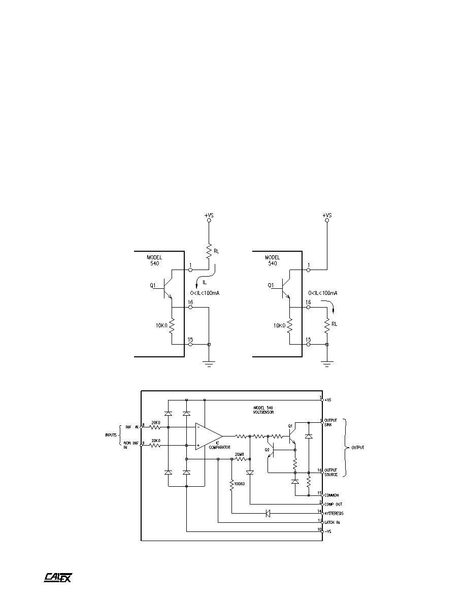
Operation
The Model 540 consists of a protected IC input stage and a
power transistor output stage. The set-point input, or
comparison voltage, can be applied to either input (pin 8 or pin
9). The varying input signal is applied to the other input. When
the voltage at pin 9 is more positive than the voltage at pin 8,
the IC comparator output switches to the high logic state and
applies a positive drive to the output power transistor Q1.
When the voltage at pin 9 is negative with respect to the
voltage at pin 8, the IC comparator will switch to the low logic
state, which is near zero volts. If the output is connected as a
current sink, (pin 16 connected to common and the load
connected between pin 1 and a positive voltage), then positive
drive from the output of the IC comparator will cause Q1 to
saturate. With Q1 switched on, the output sink can accept up
to +100 mA. A relay or lamp load at the output will be switched
to the energized condition when Q1 saturates. When the IC
comparator goes to the low state, Q1 is cut off and no current
will flow. The Voltsensor output will then rise to the positive
FIGURE 3.
FIGURE 2.
supply lead. A relay or lamp load would then be de-energized.
If the output is connected as a current source (pin 1 connected
to +VS and the output load connected between pin 16 and
common), then positive drive from the output of the IC
comparator will cause Q1 to go to a high output state. In this
mode of operation, Q1 is used as an emitter follower and it will
essentially follow the voltage output of the IC comparator.
When the IC comparator switches to the low state, the
Voltsensor output (output source, pin 16) will drop to nearly
zero volts (+50 mV maximum).
The input diodes protect the IC comparator for a maximum
input voltage of ±100V. The output stage is current limited to
140 mA in the event of a short circuit. The diode between
output source and common offers transient protection when
a relay is used as a load in the current-source mode.
External connections for the two modes of operation current
sinking and current sourcing, are shown below.
相关PDF资料 |
PDF描述 |
|---|---|
| 546 | SPECIALTY ANALOG CIRCUIT, DMA25 |
| 545 | SPECIALTY ANALOG CIRCUIT, DMA25 |
| 54752001Z5V103Z | 1 FUNCTIONS, 250 V, 15 A, FEED THROUGH CAPACITOR |
| 54FCT521LB | COMPARATOR, QCC20 |
| 54FCT521DB | COMPARATOR, CDIP20 |
相关代理商/技术参数 |
参数描述 |
|---|---|
| 540 1/2 EC | 制造商:Thomas & Betts 功能描述:SIDE BEAM HANGER CLIP |
| 540 1/2B | 制造商:Thomas & Betts 功能描述:SIDE BEAM HANGER CLIP |
| 540 1/2SS | 制造商:Thomas & Betts 功能描述:SSTRUT BEAM CLAMPS |
| 540 3/4 | 制造商:Thomas & Betts 功能描述:SIDE BEAM HANGER CLAMP |
| 540 3/4B | 制造商:Thomas & Betts 功能描述:SIDE BEAM HANGER CLIP |
发布紧急采购,3分钟左右您将得到回复。