- 您现在的位置:买卖IC网 > PDF目录117393 > 5962-0251001HXC (CRANE ELECTRONICS INC) 1-OUTPUT 8 W DC-DC REG PWR SUPPLY MODULE PDF资料下载
参数资料
| 型号: | 5962-0251001HXC |
| 厂商: | CRANE ELECTRONICS INC |
| 元件分类: | 电源模块 |
| 英文描述: | 1-OUTPUT 8 W DC-DC REG PWR SUPPLY MODULE |
| 封装: | DIP-8 |
| 文件页数: | 22/23页 |
| 文件大小: | 1291K |
| 代理商: | 5962-0251001HXC |
notes
1. guaranteed by design, not tested.
2. For MHF+281r9, load regulation is tested from a 10 ma load to full load.
3. indefinite short circuit protection not guaranteed above 125°C (case).
4. recovery time is measured from application of the transient.
to the point at which vout is within regulation.
5. Step transition time >10 s.
6. Step line is 20 - 32 - 20 vdC for MHF+281r39S.
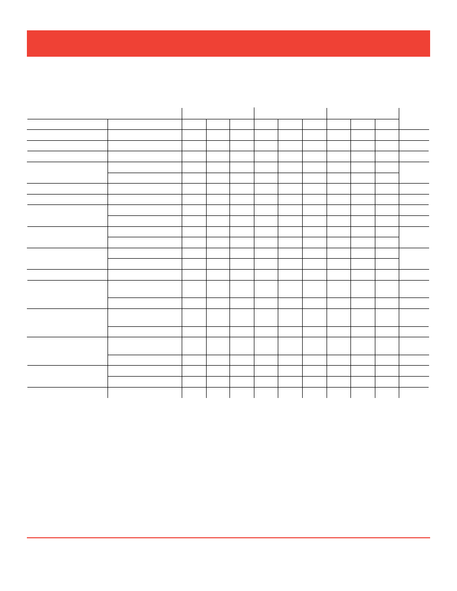
electrical Characteristics: -55° to +125°C tC , 28 vdC vin, 100% load, free run, unless otherwise specified.
Single outPut ModelS
MHF+281r9S
MHF+283r3S
MHF+2805S
unitS
paraMeter
COnDitiOnS
Min
tyP
MaX
Min
tyP
MaX
Min
tyP
MaX
Output VOltage
1.84
1.90
1.96
3.20
3.30
3.40
4.85
5.00
5.15
vdC
Output Current
Vin = 16 tO 40 VDC
0
–
3.5
0
—
2.4
0
—
2.4
a
Output pOwer
Vin = 16 tO 40 VDC
0
—
6.65
0
—
8
0
—
12
W
Output ripple
tC = 25°C
—
7
30
—
30
80
—
30
80
mv p-p
10 kHz - 2 MHz
—
12
40
—
50
240
—
60
100
line regulatiOn
Vin = 16 tO 40 VDC
—
1
40
–
5
100
—
5
50
mv
lOaD regulatiOn
nO lOaD tO Full 2
—
35
55
–
20
50
—
20
50
mv
input VOltage
nO lOaD tO Full
COntinuOuS
20
28
32
16
28
40
16
28
40
vdC
tranSient 50 ms 1
—
35
—
50
—
50
v
input Current
nO lOaD
—
16
35
—
25
40
—
25
40
ma
inHiBiteD
—
2
7
—
5
12
—
5
12
input ripple Current
tC = 25°C
—
30
60
–
45
80
—
35
80
ma p-p
10 kHz - 10 MHz
—
70
—
120
—
100
eFFiCienCy
56
62
—
67
75
–
72
77
—
%
lOaD Fault 3, 4
pOwer DiSSipatiOn
SHOrt CirCuit
—
4
8
—
5
8
—
3.5
6
W
reCOVery 1
—
5
30
—
7.5
30
—
7.5
30
ms
Step lOaD
reSpOnSe 4, 5
50% - 100% - 50%
tranSient
—
±75
±500
—
±150
±400
—
±150
±400
mv pk
reCOVery
—
500
2000
—
150
300
—
150
300
s
Step line
reSpOnSe 1, 4, 5
16 - 40 - 16 VDC 6
tranSient
—
±300
±600
—
±550
±800
—
±550
±800
mv pk
reCOVery
—
0.5
1.2
—
0.8
1.2
—
0.8
1.2
ms
Start-up 5
Delay
—
12
35
–
10
25
—
10
25
ms
OVerSHOOt 1
—
500
850
—
200
300
—
100
600
mv pk
CaPaCitive load 1
—
100
–
300
–
300
F
www.interpoint.com
Page 8 of 23
Crane aerospace & electronics Power solutions
MHF+ Single, dual and triple dC/dC Converters
28 VOlT inPuT – 15 WATT
MHF+ rev l - 20091113
相关PDF资料 |
PDF描述 |
|---|---|
| 5962F9563002VXX | 16-CHANNEL, SGL ENDED MULTIPLEXER, CDIP28 |
| 5962R0922501V9A | SWITCHING REGULATOR, UUC |
| 5S5.600UM | 1-OUTPUT 3 W DC-DC REG PWR SUPPLY MODULE |
| 5962-8670408XA | 1 A SWITCHING CONTROLLER, 500 kHz SWITCHING FREQ-MAX, CQCC20 |
| 5962-9650201QEA | 2.6 A SWITCHING REGULATOR, 173 kHz SWITCHING FREQ-MAX, CDIP16 |
相关代理商/技术参数 |
参数描述 |
|---|---|
| 5962-0251001HZA | 制造商:未知厂家 制造商全称:未知厂家 功能描述:DC to DC Converter |
| 5962-0251001HZC | 制造商:未知厂家 制造商全称:未知厂家 功能描述:DC to DC Converter |
| 5962-0251002HXA | 制造商:未知厂家 制造商全称:未知厂家 功能描述:DC to DC Converter |
| 5962-0251002HXC | 制造商:未知厂家 制造商全称:未知厂家 功能描述:DC to DC Converter |
| 5962-0251002HZA | 制造商:未知厂家 制造商全称:未知厂家 功能描述:DC to DC Converter |
发布紧急采购,3分钟左右您将得到回复。