- 您现在的位置:买卖IC网 > PDF目录63397 > 5962-9098701Q2A (TEXAS INSTRUMENTS INC) PLL FREQUENCY SYNTHESIZER, 10 MHz PDF资料下载
参数资料
| 型号: | 5962-9098701Q2A |
| 厂商: | TEXAS INSTRUMENTS INC |
| 元件分类: | PLL合成/DDS/VCOs |
| 英文描述: | PLL FREQUENCY SYNTHESIZER, 10 MHz |
| 文件页数: | 5/9页 |
| 文件大小: | 595K |
| 代理商: | 5962-9098701Q2A |
Phase Detector Operation
The phase detector on these devices is a digital circuit
that responds to the rising edges of the detector’s two in-
puts. The phase detector output has three states: a high,
5V state, a low, 0V state, and a middle, 2.5V state. In the
high and low states the output impedance of the detector
is low and the middle state output impedence is high, typi-
cally 6.0k
. When there is any static frequency difference
between the inputs, the detector output is fixed at its high
level if the +input (the sense amplifier signal) is greater in
frequency, and fixed at its low level if the -input (the refer-
ence frequency signal) is greater in frequency.
When the frequencies of the two inputs to the detector
are equal, the phase detector switches between its middle
state and either the high or low states, depending on the
relative phase of the two signals. If the +input is leading in
phase then, during each period of the input frequency, the
detector output will be high for a time equal to the time dif-
ference between the rising edges of the inputs, and will
be at its middle level for the remainder of the period. If the
phase relationship is reversed, then the detector will go
low for a time proportional to the phase difference of the
inputs. The resulting gain of the phase detector. k, is
5V/4
π radians or about 0.4V/radian. The dynamic range of
the detector is
±2π radians.
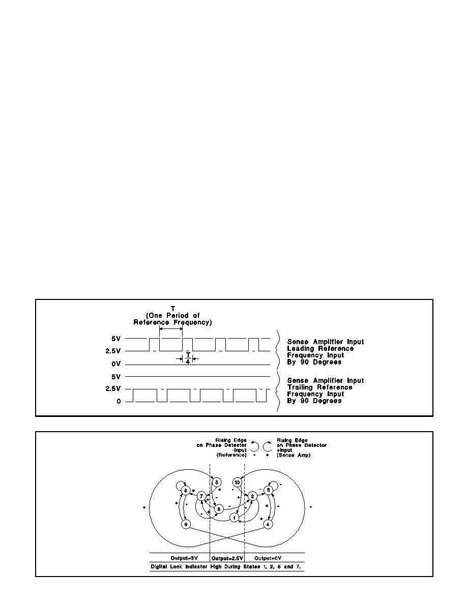
The operation of the phase detector is illustrated in the
figures below. The upper figure shows typical voltage
waveforms seen at the detector output for leading and
lagging phase conditions. The lower figure is a state dia-
gram of the phase detector logic. In this figure, the circles
represent the 10 possible states of the logic, and the con-
necting arrows represent the transition events/paths to
and from these states. Transition arrows that have a clock-
wise rotation are the result of a rising edge on the +input,
and conversely, those with counter-clockwise rotation are
tied to the rising edge of the -input signal.
The normal operational states of the logic are 6 and 7 for
positive phase error, 1 and 2 for a negative phase error.
States 8 and 9 occur during positive frequency error, 3
and 4 during negative frequency error. States 5 and 10
occur only as the inputs cross over from the frequency er-
ror to a normal phase error only condition. The level of the
phase detector output is determined by the logic state as
defined in the state diagram figure. The lock indicator out-
put is high, off, when the detector is in states 1, 2, 6, or 7.
UC1633
UC2633
UC3633
Typical Phase Detector Output Waveforms
Phase Detector State Diagram
APPLICATION AND OPERATION INFORMATION
5
相关PDF资料 |
PDF描述 |
|---|---|
| 5962-9098701QEA | PLL FREQUENCY SYNTHESIZER, 10 MHz, CDIP16 |
| 5962-9161301HZX | 2-OUTPUT 30 W DC-DC REG PWR SUPPLY MODULE |
| 5962-9210902HZX | 2-OUTPUT 30 W DC-DC REG PWR SUPPLY MODULE |
| 5962-9210901HZX | 2-OUTPUT 30 W DC-DC REG PWR SUPPLY MODULE |
| 5962-9210903HZX | 2-OUTPUT 30 W DC-DC REG PWR SUPPLY MODULE |
相关代理商/技术参数 |
参数描述 |
|---|---|
| 5962-9098903MLA | 制造商:QP Semiconductor 功能描述:Programmable Logic Arrays 24-Pin CDIP |
| 5962-9099703MRA | 制造商:Rochester Electronics LLC 功能描述:- Bulk |
| 5962-9150101MZC | 制造商:e2v Technologies 功能描述:MCU 32-Bit 68000 RISC ROMLess 5V 132-Pin CPGA |
| 5962-9150102MXA | 制造商:e2v Aerospace & Defense 功能描述:MCU 32-Bit 6800 RISC ROMLess 5V 132-Pin CQUAD |
| 5962-9150801MXA | 制造商:Integrated Device Technology Inc 功能描述:SRAM Chip Async Dual 5V 128K-Bit 16K x 8 70ns 68-Pin CPGA Tray 制造商:Integrated Device Technology Inc 功能描述:SRAM ASYNC DUAL 5V 128KBIT 16KX8 70NS 68PIN PGA - Rail/Tube |
发布紧急采购,3分钟左右您将得到回复。