- 您现在的位置:买卖IC网 > PDF目录97787 > 5962F0723201VXC (STMICROELECTRONICS) OP-AMP, 550 MHz BAND WIDTH, CDFP8 PDF资料下载
参数资料
| 型号: | 5962F0723201VXC |
| 厂商: | STMICROELECTRONICS |
| 元件分类: | 运算放大器 |
| 英文描述: | OP-AMP, 550 MHz BAND WIDTH, CDFP8 |
| 封装: | ROHS COMPLIANT, HERMETIC SEALED, CERAMIC, FP-8 |
| 文件页数: | 2/20页 |
| 文件大小: | 397K |
| 代理商: | 5962F0723201VXC |
Power supply considerations
RHF350
10/20
Doc ID 15604 Rev 2
3
Power supply considerations
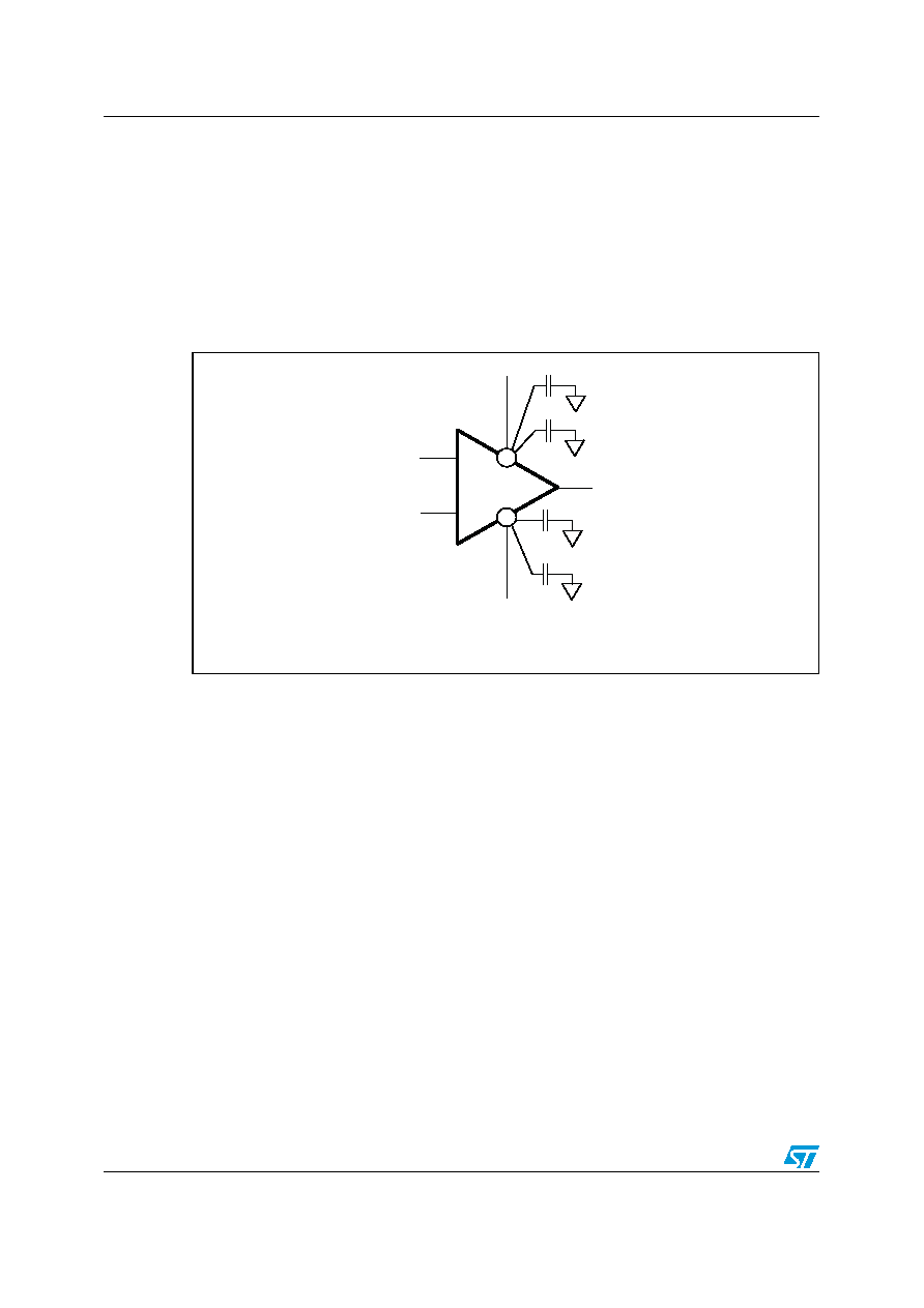
Correct power supply bypassing is very important to optimize performance in high-
frequency ranges. The bypass capacitors should be placed as close as possible to the IC
pins to improve high-frequency bypassing. A capacitor greater than 1
μF is necessary to
minimize the distortion. For better quality bypassing, a 10 nF capacitor can be added. It
should also be placed as close as possible to the IC pins. The bypass capacitors must be
incorporated for both the negative and positive supply.
Figure 24.
Circuit for power supply bypassing
3.1
Single power supply
In the event that a single supply system is used, biasing is necessary to obtain a positive
output dynamic range between the 0 V and +VCC supply rails. Considering the values of
VOH and VOL, the amplifier provides an output swing from +0.9 V to +4.1 V on a 100 Ω load.
The amplifier must be biased with a mid-supply (nominally +VCC/2), in order to maintain the
DC component of the signal at this value. Several options are possible to provide this bias
supply, such as a virtual ground using an operational amplifier or a two-resistance divider
(which is the cheapest solution). A high resistance value is required to limit the current
consumption. On the other hand, the current must be high enough to bias the non-inverting
input of the amplifier. If we consider this bias current (35
μA maximum) as 1% of the current
through the resistance divider, to keep a stable mid-supply two resistances of 750
Ω can be
used.
The input provides a high-pass filter with a break frequency below 10 Hz which is necessary
to remove the original 0 V DC component of the input signal, and to set it at +VCC/2.
illustrates a 5 V single power supply configuration. A capacitor CG is
added to the gain network to ensure a unity gain at low frequencies in order to keep the right
DC component at the output. CG contributes to a high-pass filter with Rfb//RG and its value is
calculated with regard to the cut-off frequency of this low-pass filter.
+
+V
CC
10 F
+
10 nF
10 F
+
10 nF
-
-V
CC
AM00835
相关PDF资料 |
PDF描述 |
|---|---|
| 5962F9683401VCA | QUAD BUFFER AMPLIFIER, CDIP14 |
| 5962F9683401VCC | QUAD BUFFER AMPLIFIER, CDIP14 |
| 5962F9683401VCA | QUAD BUFFER AMPLIFIER, CDIP14 |
| 5962F9683401VCX | QUAD BUFFER AMPLIFIER, CDIP14 |
| 5962L9950401VCA | QUAD OP-AMP, 7000 uV OFFSET-MAX, 1 MHz BAND WIDTH, CDIP14 |
相关代理商/技术参数 |
参数描述 |
|---|---|
| 5962F1023501KXA | 制造商:International Rectifier 功能描述:RAD HARD ULDO - Bulk |
| 5962F1023502K4A | 制造商:International Rectifier 功能描述:RAD HARD ULDO - Bulk |
| 5962F1023502K5A | 制造商:International Rectifier 功能描述:RAD HARD ULDO - Bulk |
| 5962F1023502K6A | 制造商:International Rectifier 功能描述:RAD HARD ULDO - Bulk |
| 5962F1023502KYA | 制造商:International Rectifier 功能描述:RAD HARD ULDO - Bulk |
发布紧急采购,3分钟左右您将得到回复。