- 您现在的位置:买卖IC网 > PDF目录97787 > 5962R9863901VGX (ANALOG DEVICES INC) OP-AMP, 400 uV OFFSET-MAX, MBCY8 PDF资料下载
参数资料
| 型号: | 5962R9863901VGX |
| 厂商: | ANALOG DEVICES INC |
| 元件分类: | 运算放大器 |
| 英文描述: | OP-AMP, 400 uV OFFSET-MAX, MBCY8 |
| 封装: | METAL CAN-8 |
| 文件页数: | 11/13页 |
| 文件大小: | 72K |
| 代理商: | 5962R9863901VGX |
STANDARD
MICROCIRCUIT DRAWING
SIZE
A
5962-98639
DEFENSE SUPPLY CENTER COLUMBUS
COLUMBUS, OHIO 43216-5000
REVISION LEVEL
A
SHEET
7
DSCC FORM 2234
APR 97
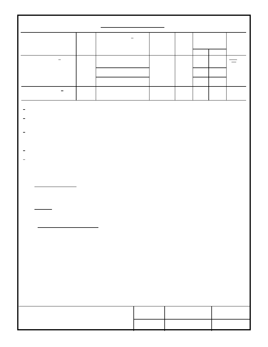
TABLE I. Electrical performance characteristics - Continued.
Test
Symbol
Conditions 1/
-55
°C ≤ TA ≤ +125°C
unless otherwise specified
Group A
subgroups
Device
type
Limits
Unit
Min
Max
Input noise voltage 4/
density
En
fO = 10 Hz
4
01
18
nV
√Hz
fO = 100 Hz
14
fO = 1 kHz
12
Low frequency input 4/
noise voltage
Enpp
fO = 0.1 Hz to 10 Hz
4
01
0.6
VPP
1/
±VS = ±15 V and VCM = 0 V.
2/ Due to the inherent warm-up drift of device type 01, testing shall occur no sooner than five minutes after application of
power.
3/ Devices supplied to this drawing have been characterized through all levels M, D, P, L, and R of irradiation. However,
this device is only tested at the "R" level. Pre and Post irradiation values are identical unless otherwise specified
in table I. When performing post irradiation electrical measurements for any RHA level, TA = +25
°C.
4/ This parameter is not tested to post irradiation.
5/ Continuous short circuit limits are considerably less than the indicated test limits since maximum power dissipation
cannot be exceeded.
4. QUALITY ASSURANCE PROVISIONS
4.1 Sampling and inspection. For device classes Q and V, sampling and inspection procedures shall be in accordance with MIL-
PRF-38535 or as modified in the device manufacturer's Quality Management (QM) plan. The modification in the QM plan shall not
affect the form, fit, or function as described herein. For device class M, sampling and inspection procedures shall be in accordance
with MIL-PRF-38535, appendix A.
4.2 Screening. For device classes Q and V, screening shall be in accordance with MIL-PRF-38535, and shall be conducted on
all devices prior to qualification and technology conformance inspection. For device class M, screening shall be in accordance with
method 5004 of MIL-STD-883, and shall be conducted on all devices prior to quality conformance inspection.
4.2.1 Additional criteria for device class M.
a.
Burn-in test, method 1015 of MIL-STD-883.
(1) Test condition A, B, C, or D. The test circuit shall be maintained by the manufacturer under document revision level
control and shall be made available to the preparing or acquiring activity upon request. The test circuit shall specify
the inputs, outputs, biases, and power dissipation, as applicable, in accordance with the intent specified in test
method 1015.
(2) TA = +125
°C, minimum.
b.
Interim and final electrical test parameters shall be as specified in table IIA herein.
相关PDF资料 |
PDF描述 |
|---|---|
| 5962R9863901VHX | OP-AMP, 400 uV OFFSET-MAX, CDFP10 |
| 5962R9863901VPX | OP-AMP, 400 uV OFFSET-MAX, CDIP8 |
| 5962R9863901V2A | OP-AMP, 400 uV OFFSET-MAX, CQCC20 |
| 5962R9863901VGA | OP-AMP, 400 uV OFFSET-MAX, MBCY8 |
| 5962R9863901VHA | OP-AMP, 400 uV OFFSET-MAX, CDFP10 |
相关代理商/技术参数 |
参数描述 |
|---|---|
| 5962R9863901VHA | 制造商:Analog Devices 功能描述:OP AMP SGL GP 20V 10PIN FLATPACK - Rail/Tube |
| 5962R9864602VXA | |
| 5962R9950401VCA | 功能描述:线性稳压器 - 标准 RoHS:否 制造商:STMicroelectronics 输出类型: 极性: 输出电压:1.8 V 输出电流:150 mA 负载调节: 最大输入电压:5.5 V 线路调整率: 最大工作温度:+ 125 C 安装风格:SMD/SMT 封装 / 箱体:SOT-323-5L |
| 5962R9950401VDA | 功能描述:线性稳压器 - 标准 RoHS:否 制造商:STMicroelectronics 输出类型: 极性: 输出电压:1.8 V 输出电流:150 mA 负载调节: 最大输入电压:5.5 V 线路调整率: 最大工作温度:+ 125 C 安装风格:SMD/SMT 封装 / 箱体:SOT-323-5L |
| 5962R9950401VZA | 功能描述:线性稳压器 - 标准 RoHS:否 制造商:STMicroelectronics 输出类型: 极性: 输出电压:1.8 V 输出电流:150 mA 负载调节: 最大输入电压:5.5 V 线路调整率: 最大工作温度:+ 125 C 安装风格:SMD/SMT 封装 / 箱体:SOT-323-5L |
发布紧急采购,3分钟左右您将得到回复。