- 您现在的位置:买卖IC网 > PDF目录249562 > 61117-6 (Tyco Electronics) .200" Centerline, 250 V, 13 A max. PDF资料下载
参数资料
| 型号: | 61117-6 |
| 厂商: | Tyco Electronics |
| 元件分类: | 终端 |
| 英文描述: | .200" Centerline, 250 V, 13 A max. |
| 中文描述: | .200" 间距, 250 V, 13 A 最大值 |
| 文件页数: | 25/98页 |
| 文件大小: | 2948K |
| 代理商: | 61117-6 |
第1页第2页第3页第4页第5页第6页第7页第8页第9页第10页第11页第12页第13页第14页第15页第16页第17页第18页第19页第20页第21页第22页第23页第24页当前第25页第26页第27页第28页第29页第30页第31页第32页第33页第34页第35页第36页第37页第38页第39页第40页第41页第42页第43页第44页第45页第46页第47页第48页第49页第50页第51页第52页第53页第54页第55页第56页第57页第58页第59页第60页第61页第62页第63页第64页第65页第66页第67页第68页第69页第70页第71页第72页第73页第74页第75页第76页第77页第78页第79页第80页第81页第82页第83页第84页第85页第86页第87页第88页第89页第90页第91页第92页第93页第94页第95页第96页第97页第98页

165
Catalog 82181
Dimensions are in inches and
Dimensions are shown for
USA: 1-800-522-6752
South America: 55-11-2103-6000
Revised 4-08
millimeters unless otherwise
reference purposes only.
Canada: 1-905-470-4425
Hong Kong: 852-2735-1628
specified. Values in brackets
Specifications subject
Mexico: 01-800-733-8926
Japan: 81-44-844-8013
www.tycoelectronics.com
are metric equivalents.
to change.
C. America: 52-55-1106-0803
UK: 44-8706-080-208
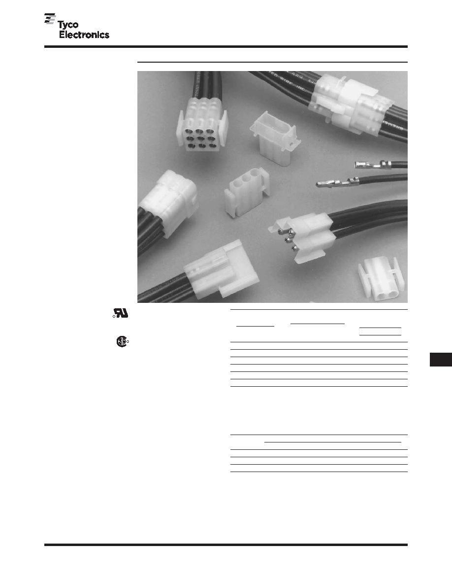
.140 MATE-N-LOK Connectors (Large Insulation), .240 Centerline
AMP
Soft Shell
Pin and Socket Connectors
Standard
Density
.140
MA
TE-N-LOK
Connectors
(Large
Insulation)
.240
[6.10]
Centerline
Maximum Current—Maximum cur-
rent rating of .140 MATE-N-LOK
Connectors is limited by the maximum
operating temperature of the housings
which is 105°C and the temperature rise
of the contacts which is 30°C. There are
several variables which have a direct
effect on this maximum current-carrying
capability for a given connector and
must be considered for each application.
These variables are:
Wire Size—Larger diameter wire will
carry more current since it has less inter-
nal resistance to current flow and thus
generates less heat. Longer wire lengths
also enhance current-carrying capabili-
ties since the wire conducts heat away
from the connector.
Connector Size—In general, the more
circuits in a connector, the less current
can be carried.
Ambient Temperature—The higher
the ambient temperature, the less current
can be carried in any given connector.
Technical Documents
Product Specification
108-1032
.140 Diameter
MATE-N-LOK Connectors
Application Specification
114-1007
.140 Diameter
MATE-N-LOK Contacts
Termination
Contact
Resistance
Crimp
Wire Size
Test
Resistance
Tensile Force
AWG
mm2
Current
Milliohms
Force (Min.)
(Amps)
(Max. Init.)
lbs.
N
20
.5
4.5
3.0
20
89
18
.8
6
2.5
30
133
16
1.2
8
2.5
45
200
14
2.0
10
2.0
50
222
12
3.0
12
1.5
60
267
10
5.0
14
1.5
65
289
Note: This is the total resistance between wire crimps of a mated pin and socket.
Product Facts
I
Available in 2, 3 and 9
circuit configurations for
panel mounting; 4 and 9
circuit configurations for
free-hanging applications
I
Standard natural nylon
housings
I
Housings fully polarized
I
Contacts fully protected in
housings
I
Contacts accept wire
size range 20-10 AWG
[.5-5.0 mm2] with insulation
diameters from .100 [2.54]
to .180 [4.57]
I
Low insertion/extraction
forces
I
Dual locking lances provide
optimum contact stability
I
Extraction tool removes both
pins and sockets
I
Contacts are on .240 [6.09]
centerline spacing
I
Not for interrupting current
I
Recognized under the
Component Program
of Underwriters
Laboratories Inc.,
File No. E28476
I
Certified by Canadian
Standards Association,
File No. LR 7189A
Performance Characteristics
The .140 MATE-N-LOK Connector per-
formance characteristics found on this
page are based on free-hanging and
panel mount connectors, loaded with
contacts crimped on stranded wire.
Dielectric Withstand Voltage—
3.0 KVAC between adjacent circuits
Insulation Resistance—
1000 megohms minimum initial between
adjacent circuits
Voltage Rating—600 V AC or DC
Connector Mating—4.5 lb. max. per
circuit
Connector Unmating—.8 lb. min. per
circuit
Contact Retention—30 lb. min.
Durability—25 cycles, mating and
unmating
Thermal Shock— -55°C to +85°C
Temperature-Humidity Cycling—
25°C to 65°C at 95 RH
Current Rating Verification for 30°C Maximum Temperature Rise
100% Energized
Wire-to-Wire
.140 MATE-N-LOK Connector Calculated Current Table
Number of
Wire AWG
Circuits
10
12
14
16
18
20
2
28.00
23.00
18.50
15.00
13.50
10.50
3
25.00
21.00
17.00
13.50
12.00
9.50
9
18.50
15.00
12.00
10.00
9.00
7.00
Values are based on initial Temperature Rise versus Current Testing and are
intended to be a guide in the selection of a connector family. All applications
should be tested by the end user. The values listed are per circuit for fully
loaded housings being 100% energized. Note: All combinations were not
tested, and this chart contains interpolated and extrapolated values.
Minimum Wire Lengths for T-Rise vs. Current Testing
Note: If wire lengths used are less than those listed, the current carrying
ability of the system will be reduced due to less heat being conducted away
from the connector. The customer should fully test all applications.
R
相关PDF资料 |
PDF描述 |
|---|---|
| 61117-7 | .200" Centerline, 250 V, 13 A max. |
| 61118-1 | .200" Centerline, 250 V, 13 A max. |
| 61118-2 | .200" Centerline, 250 V, 13 A max. |
| 61118-4 | .200" Centerline, 250 V, 13 A max. |
| 61118-5 | .200" Centerline, 250 V, 13 A max. |
相关代理商/技术参数 |
参数描述 |
|---|---|
| 6111-764 | 制造商:Megger 功能描述:LCMD CD |
| 61117-7 | 功能描述:电源到板 SOK 20-14 AUBR 5000 RoHS:否 制造商:TE Connectivity / AMP 系列:5787444 产品类型:Connectors 触点类型: 电压额定值:50 V 电流额定值: 节距: 位置/触点数量:5 安装风格:Through Hole 端接类型: 触点电镀:Tin |
| 611177-516 | 制造商:Mitutoyo Corporation 功能描述:0.137", RECT, STEEL, ASME K |
| 61117-C-W | 制造商:Molex 功能描述: |
| 61117-C-W-50 | 制造商:Molex 功能描述: |
发布紧急采购,3分钟左右您将得到回复。