- 您现在的位置:买卖IC网 > PDF目录249728 > 6N140AOPTION60 (ISOCOM LTD) 4 CHANNEL LOGIC OUTPUT OPTOCOUPLER PDF资料下载
参数资料
| 型号: | 6N140AOPTION60 |
| 厂商: | ISOCOM LTD |
| 元件分类: | 光电耦合器 |
| 英文描述: | 4 CHANNEL LOGIC OUTPUT OPTOCOUPLER |
| 封装: | ROHS COMPLIANT, HERMETIC SEALED, CERAMIC, SURFACE MOUNT, DIP-16 |
| 文件页数: | 2/12页 |
| 文件大小: | 443K |
| 代理商: | 6N140AOPTION60 |
ISOCOMLTD
For sales enquiries, or further information, please contact our sales office at:
Isocom Ltd, Hutton Close, Crowther Industrial Estate, District 3, Washington, NE38 0AH
Tel: +44 0191 4166 546 Fax: +44 0191 4155 055
2007 Copyright reserved to Isocom Limited
Page 10 of 12
QC 88000-C001: 2007
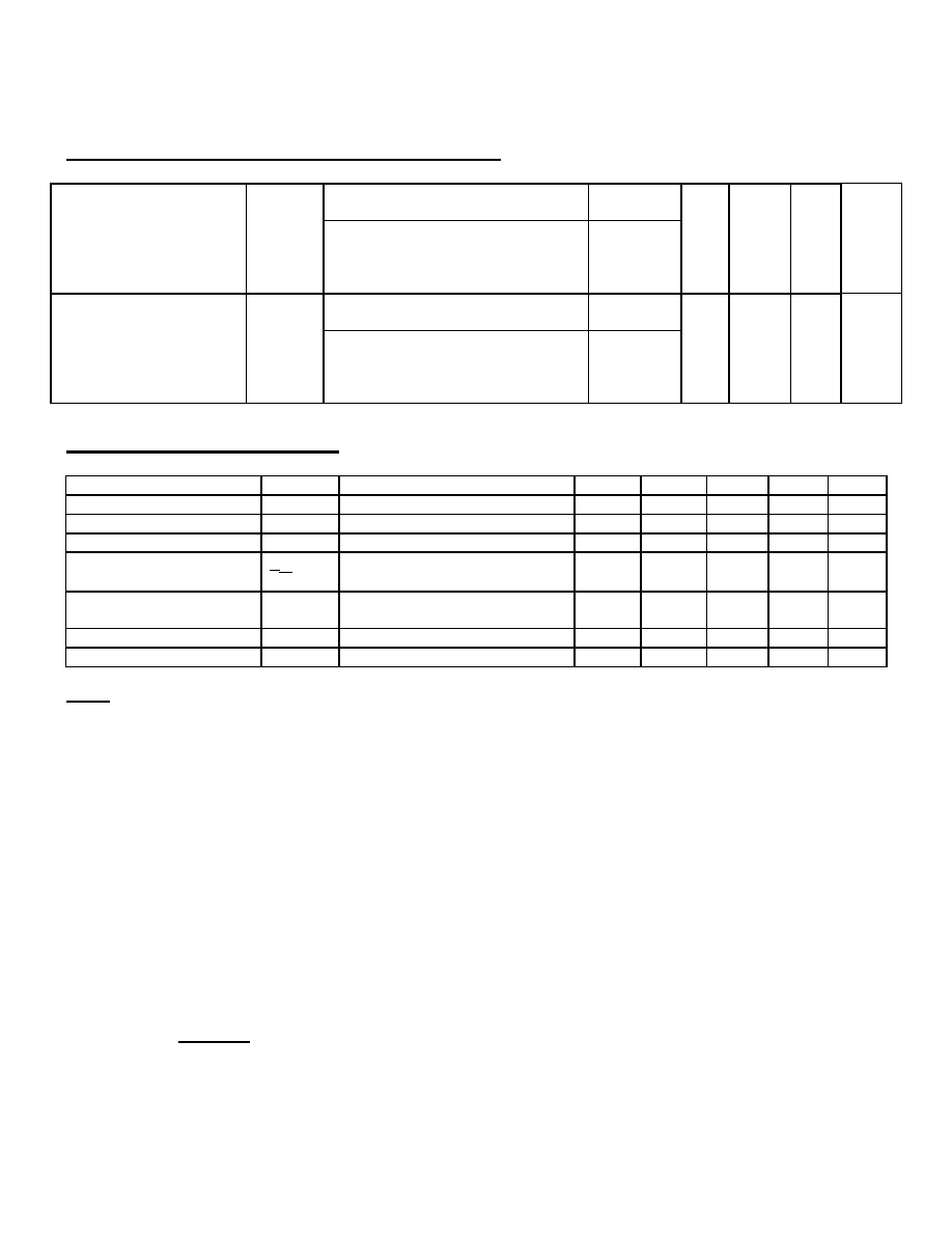
Electrical Characteristics (Continued)
VCC = 5V, TA = 25°C, VCM = 50V p-p
RL = 1.5K , IF = 0Ma
Common Mode Transient
Immunity at Logical High
Output Level
(See notes 4, 10 & 12)
CMH
RL = 2.2K , IF = 0mA
CH370
CS700
CSM1700
CSM6730
500
1000
-
V/S
VCC = 5V, TA = 25°C, VCM = 50V p-p
RL = 1.5K , IF = 1.6mA
Common Mode Transient
Immunity at Logical Low
Output Level
(See notes 4, 10 & 12)
CML
RL = 2.2K , IF = 1.6mA
CH370
CS700
CSM1700
CSM6730
500
-1000
-
V/S
Typical Characteristics
TA = 25°C
Parameter
Symbol
Test Conditions
Notes
Min
Type
Max
Units
Resistance
RIO
V10 = 500Vdc
4 & 8
-
10
12
-
Capacitance
CIO
f = 1MHz
4 & 8
-
1.5
-
pF
Input Capacitance
CIN
f = 1MHz, VF = 0
4
-
60
-
pF
Temperature Coefficient
of Forward Voltage
VF
TA
IF = 1.6mA
1
-
-1.8
-
mV/°
C
Input-Input Insulation
Leakage Current
II-I
45% Relative Humidity
VII = 500Vdc, t = 5S
9
-
0.6
-
nA
Resistance
RI-I
VII = 500Vdc
9
-
10
12
-
Capacitance
CI-I
f = 1MHz
9
-
1
-
pF
Notes:
1. The ground pin should be the most negative voltage at the detector side. Keeping VCC as low as possible, but
greater than 2.0V, will provide lowest total IOH over temperature.
2. Output power is collector output plus one fourth of total supply power. Derate at 1.66mW/°C above 110°C.
3. Derate IF at 0.33mA/°C above 110°C.
4. Each channel.
5. Current Transfer Ratio is defined as the ratio of output collector current, IO, to the forward LED input current, IF, times
100%.
6. IOHX is the leakage current resulting from channel to channel optical crosstalk. IF = 2A for channel under test. For all
other channels, IF = 10mA.
7. Input pins are shorted together, and output pins are shorted together.
8. Measured between the LED anode and cathode shorted together and pins at output shorted together.
9. Measured between adjacent input pairs shorted together.
10. CMH is the maximum tolerable common mode transient to assure that the output will remain in a high logic state
(i.e., VO > 2.0V).
11. CML is the maximum tolerable common mode transient to assure that the output will remain in the logic low state
(i.e., VO< 0.8V).
12. In applications where dV/dt may exceed 50,000V/S (such as a static discharge), a series resistor, RCC, should be
included to protect the detector IC’s from destructively high surge currents. The recommended value is
RCC =
1V
k
0.6IF(mA)
13. This is a momentary withstand test, not an operating condition.
相关PDF资料 |
PDF描述 |
|---|---|
| 678-114-21-07 | SINGLE COLOR LED, GREEN, 10 mm |
| 678-105-21-12 | SINGLE COLOR LED, RED, 10 mm |
| 62V05-01-205CT | SINGLE, 2 CHANNELS, ROTARY OPTICAL POSITION ENCODER |
| 62V05-01-060CHT | SINGLE, 2 CHANNELS, ROTARY OPTICAL POSITION ENCODER |
| 62V03-02-160CHT | SINGLE, 2 CHANNELS, ROTARY OPTICAL POSITION ENCODER |
相关代理商/技术参数 |
参数描述 |
|---|---|
| 6N140ATXV | 制造商:未知厂家 制造商全称:未知厂家 功能描述:Optoelectronic |
| 6N140TXV | 功能描述:逻辑输出光电耦合器 4Ch 1500%CTR Hermetically sealed RoHS:否 制造商:Fairchild Semiconductor 绝缘电压:4243 Vrms 输出类型:Push-Pull 最大传播延迟时间:500 ns 最大正向二极管电压: 最大反向二极管电压: 最大正向二极管电流: 最大连续输出电流:2.5 A 最大功率耗散:100 mW 最大工作温度:+ 100 C 最小工作温度:- 40 C 封装 / 箱体:SO-16 封装:Tube |
| 6N140TXVB | 功能描述:逻辑输出光电耦合器 4Ch 1500%CTR Hermetically sealed RoHS:否 制造商:Fairchild Semiconductor 绝缘电压:4243 Vrms 输出类型:Push-Pull 最大传播延迟时间:500 ns 最大正向二极管电压: 最大反向二极管电压: 最大正向二极管电流: 最大连续输出电流:2.5 A 最大功率耗散:100 mW 最大工作温度:+ 100 C 最小工作温度:- 40 C 封装 / 箱体:SO-16 封装:Tube |
| 6N-20 | 制造商:Aeroflex / Inmet 功能描述:ATTENUATOR - FIXED COAXIAL |
| 6N20W-03 | 制造商:Aeroflex / Inmet 功能描述:ATTENUATOR - FIXED COAXIAL |
发布紧急采购,3分钟左右您将得到回复。