- 您现在的位置:买卖IC网 > PDF目录20604 > 71M6513H-IGTR/F (Maxim Integrated)IC ENERGY METER 3PH 100-LQFP PDF资料下载
参数资料
| 型号: | 71M6513H-IGTR/F |
| 厂商: | Maxim Integrated |
| 文件页数: | 9/104页 |
| 文件大小: | 0K |
| 描述: | IC ENERGY METER 3PH 100-LQFP |
| 产品培训模块: | Lead (SnPb) Finish for COTS Obsolescence Mitigation Program |
| 标准包装: | 1,000 |
| 系列: | Single Converter Technology® |
| 测量误差: | 0.1% |
| 电源电压: | 3 V ~ 3.6 V |
| 测量仪表类型: | 3 相 |
| 工作温度: | -40°C ~ 85°C |
| 安装类型: | 表面贴装 |
| 封装/外壳: | 100-LQFP |
| 供应商设备封装: | 100-LQFP(14x14) |
| 包装: | 带卷 (TR) |
第1页第2页第3页第4页第5页第6页第7页第8页当前第9页第10页第11页第12页第13页第14页第15页第16页第17页第18页第19页第20页第21页第22页第23页第24页第25页第26页第27页第28页第29页第30页第31页第32页第33页第34页第35页第36页第37页第38页第39页第40页第41页第42页第43页第44页第45页第46页第47页第48页第49页第50页第51页第52页第53页第54页第55页第56页第57页第58页第59页第60页第61页第62页第63页第64页第65页第66页第67页第68页第69页第70页第71页第72页第73页第74页第75页第76页第77页第78页第79页第80页第81页第82页第83页第84页第85页第86页第87页第88页第89页第90页第91页第92页第93页第94页第95页第96页第97页第98页第99页第100页第101页第102页第103页第104页
�� ��
��
 ��
��71M6513/71M6513H�
�A� Maxim� Integrated� Products� Brand�
�3� -Phase Energy Meter IC�
�I� C� interface� and� an� optical/IR� interface.�
�DATA� SHEET�
�SEPTEMBER� 2011�
�HARDWARE� DESCRIPTION�
�Hardware� Overview�
�The� 71M6513� single-chip� polyphase� meter� integrates� all� primary� functional� blocks� required� to� implement� a� solid-state�
�electricity� meter.� Included� on� chip� are� an� analog� front� end� (AFE),� an� 8051-compatible� microprocessor� (MPU)� which� executes�
�one� instruction� per� clock� cycle� (80515),� an� independent� 32-bit� digital� computation� engine� (CE),� a� voltage� reference,� a�
�temperature� sensor,� LCD� drivers,� RAM,� flash� memory,� a� real� time� clock� (RTC),� and� a� variety� of� I/O� pins.� Various� current�
�sensor� technologies� are� supported� including� Current� Transformers� (CT),� Resistive� Shunts,� and� Rogowski� (� di/dt)� Coils.�
�In� addition� to� advanced� measurement� functions,� the� real� time� clock� function� allows� the� 71M6513/6513H� to� record� time� of� use�
�(TOU)� metering� information� for� multi-rate� applications.� Measurements� can� be� displayed� on� either� a� 3V� or� a� 5V� LCD.� Flexible�
�mapping� of� LCD� display� segments� will� facilitate� integration� with� any� LCD� format.� The� design� trade-off� between� the� number� of�
�LCD� segments� and� DIO� pins� can� be� flexibly� configured� using� memory-mapped� I/O� to� accommodate� various� requirements.�
�The� 71M6513� includes� several� I/O� peripheral� functions� that� improve� the� functionality� of� the� device� and� reduce� the� component�
�count� for� most� meter� applications.� The� I/O� peripherals� include� two� UARTs,� digital� I/O,� comparator� inputs,� LCD� display� drivers,�
�2�
�One� of� the� two� internal� UARTs� (UART1)� is� adapted� to� support� an� Infrared� LED� with� internal� drive� output� and� sense� input� but� it�
�can� also� function� as� a� standard� UART.�
�A� block� diagram� of� the� chip� is� shown� in� Figure� 1.� A� detailed� description� of� various� hardware� blocks� follows.�
�Analog� Front� End� (AFE)�
�The� AFE� of� the� 71M6513� Power� Meter� IC� is� comprised� of� an� input� multiplexer,� a� delta-sigma� A/D� converter� with� a� voltage�
�reference,� followed� by� an� FIR� filter.� A� block� diagram� of� the� AFE� is� shown� in� Figure� 3.�
�Multiplexer�
�The� input� multiplexer� supports� eight� input� signals� that� are� applied� to� the� pins� IA,� VA,� IB,� VB,� IC,� VC,� and� V3� plus� the� output� of�
�the� internal� temperature� sensor.� The� multiplexer� can� be� operated� in� two� modes:�
�?�
�?�
�During� a� normal� multiplexer� cycle,� the� signals� from� the� six� pins� IA,� VA,� IB,� VB,� IC,� and� VC� are� selected.�
�During� the� alternate� multiplexer� cycle,� the� temperature� signal� (TEMP)� and� the� additional� monitor� input,� V3,� are�
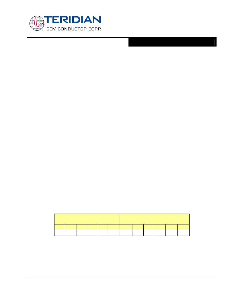
�selected,� along� with� the� other� signal� sources� shown� in� Table� 1:� Inputs� Selected� in� Regular� and� Alternate� Multiplexer�
�Cycles.�
�Alternate� multiplexer� cycles� are� usually� performed� infrequently� (every� second� or� so).� VA,� VB,� and� VC� are� not� replaced� in� the�
�alternate� multiplexer� cycles.� In� some� equations,� currents� must� be� delayed� in� allpass� networks� and� therefore� cannot� be�
�replaced� in� the� alternate� selection.� Missing� samples� due� to� alternate� multiplexer� cycles� are� automatically� interpolated� by� the�
�CE.�
�Regular� multiplexer� sequence�
�Mux� State:�
�Alternate� multiplexer� sequence�
�Mux� State:�
�0�
�IA�
�1�
�VA�
�2�
�IB�
�3�
�VB�
�4�
�IC�
�5�
�VC�
�0�
�TEMP�
�1�
�VA�
�2�
�V3�
�3�
�VB�
�4�
�IC�
�5�
�VC�
�Table� 1:� Inputs� Selected� in� Regular� and� Alternate� Multiplexer� Cycles�
�In� a� typical� application,� the� IA,� IB,� and� IC� inputs� are� connected� to� current� transformers� that� sense� the� current� on� each� phase� of�
�the� line� voltage.� VA,� VB,� and� VC� are� typically� connected� to� voltage� sensors� through� resistor� dividers.�
�The� Multiplexer� Control� Circuit� handles� the� setting� of� the� multiplexer.� The� function� of� the� Multiplexer� Control� Circuit� is�
�governed� by� the� I/O� RAM� registers� MUX_ALT� (0x2005[2]),� EQU� (0x2000[7:5]),� and� MUX_DIV� (0x2002[7:6]).� MUX_DIV� controls�
�the� number� of� samples� per� cycle.� It� can� request� 2,� 3,� 4,� or� 6� multiplexer� states� per� cycle.�
�?� 2005-2011� Teridian� Semiconductor� Corporation�
�Page:� 9� of� 104�
�相关PDF资料 |
PDF描述 |
|---|---|
| 78M6618-MR/F/P1 | IC PWR MEASUREMENT OCTAL 68QFN |
| VI-BNV-EU-F3 | CONVERTER MOD DC/DC 5.8V 200W |
| R1S12-0524/H | CONV DC/DC 1W 05VIN 24VOUT |
| 71M6533H-IGTR/F | IC ENERY METER 3PH 128K 100-LQFP |
| VI-BNV-EU-F1 | CONVERTER MOD DC/DC 5.8V 200W |
相关代理商/技术参数 |
参数描述 |
|---|---|
| 71M6513-IEL | 制造商:未知厂家 制造商全称:未知厂家 功能描述:71M6513 |
| 71M6513-IEL/F | 功能描述:计量片上系统 - SoC 3-Phase Energy Meter I/C RoHS:否 制造商:Maxim Integrated 核心:80515 MPU 处理器系列:71M6511 类型:Metering SoC 最大时钟频率:70 Hz 程序存储器大小:64 KB 数据 RAM 大小:7 KB 接口类型:UART 可编程输入/输出端数量:12 片上 ADC: 安装风格:SMD/SMT 封装 / 箱体:LQFP-64 封装:Reel |
| 71M6513-IELR/F | 制造商:Maxim Integrated Products 功能描述:Metering Systems on a Chip - SoC 3-Phase Energy Meter I/C |
| 71M6513-IGT/F | 功能描述:计量片上系统 - SoC 3-Phase Energy Meter I/C RoHS:否 制造商:Maxim Integrated 核心:80515 MPU 处理器系列:71M6511 类型:Metering SoC 最大时钟频率:70 Hz 程序存储器大小:64 KB 数据 RAM 大小:7 KB 接口类型:UART 可编程输入/输出端数量:12 片上 ADC: 安装风格:SMD/SMT 封装 / 箱体:LQFP-64 封装:Reel |
| 71M6513-IGT/F1 | 功能描述:计量片上系统 - SoC RoHS:否 制造商:Maxim Integrated 核心:80515 MPU 处理器系列:71M6511 类型:Metering SoC 最大时钟频率:70 Hz 程序存储器大小:64 KB 数据 RAM 大小:7 KB 接口类型:UART 可编程输入/输出端数量:12 片上 ADC: 安装风格:SMD/SMT 封装 / 箱体:LQFP-64 封装:Reel |
发布紧急采购,3分钟左右您将得到回复。