- 您现在的位置:买卖IC网 > PDF目录97839 > 71M6515H-IGTW/F (MAXIM INTEGRATED PRODUCTS INC) SPECIALTY ANALOG CIRCUIT, PQFP64 PDF资料下载
参数资料
| 型号: | 71M6515H-IGTW/F |
| 厂商: | MAXIM INTEGRATED PRODUCTS INC |
| 元件分类: | 模拟信号调理 |
| 英文描述: | SPECIALTY ANALOG CIRCUIT, PQFP64 |
| 封装: | LEAD FREE, LQFP-64 |
| 文件页数: | 18/60页 |
| 文件大小: | 826K |
| 代理商: | 71M6515H-IGTW/F |
第1页第2页第3页第4页第5页第6页第7页第8页第9页第10页第11页第12页第13页第14页第15页第16页第17页当前第18页第19页第20页第21页第22页第23页第24页第25页第26页第27页第28页第29页第30页第31页第32页第33页第34页第35页第36页第37页第38页第39页第40页第41页第42页第43页第44页第45页第46页第47页第48页第49页第50页第51页第52页第53页第54页第55页第56页第57页第58页第59页第60页
71M6515H
Energy Meter IC
DATA SHEET
JULY 2011
Page: 25 of 60
2005
2011 Teridian Semiconductor Corporation
1.6
A Maxim Integrated Products Brand
General Notes on Calibration
The calibration procedures described below should be followed after
interfacing the voltage and current sensors to the 71M6515H chip. When
properly interfaced, the V3P3 power supply is connected to the meter
neutral and is the DC reference for each input. Each voltage and current
waveform, as seen by the 6515H, is scaled to be less than 250mV
(peak).
Each meter phase must be calibrated individually. The procedures below
show how to calibrate a meter phase with either three or five
measurements. Note that there is no need to calibrate for VARh if the
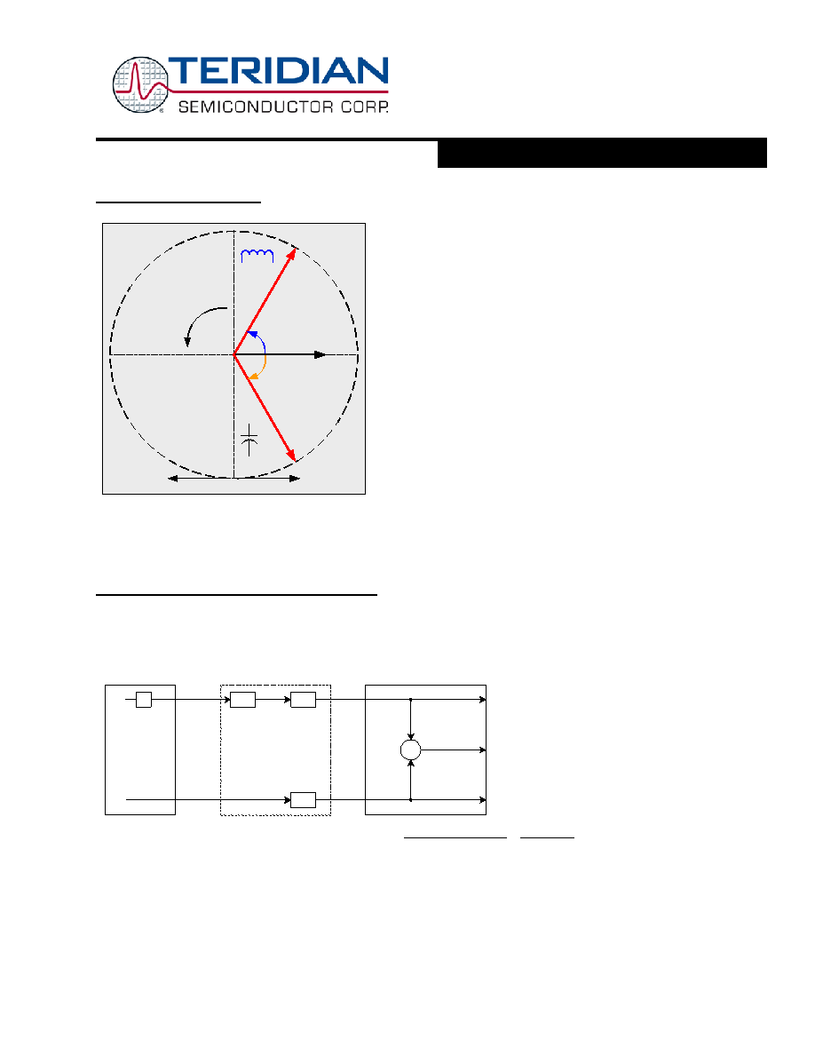
Wh measurement is calibrated correctly. Note that positive load angles
correspond to lagging current (see Figure 12).
For a typical calibration, a meter calibration system is used to apply a
calibrated load, e.g. 240V at 30A, while interfacing the voltage and
current sensors to the 71M6515H. This load should result in an ob-
servable pulse rate at the PULSEW output depending on the selected
energy per pulse. For example, 7.2kW will result in an energy rate
corresponding to 7200Wh/3600s = 2Wh/s, i.e., when 7.2kW are applied
per phase (resulting in a total power of 21.6kW, equivalent to 6Wh/s) and
a Kh of 3.2 (Wh/pulse) has been configured, a pulse rate of 6Wh/3.2Whs
= 1.875Hz will be established.
Figure 12: Definition of Load Angles
It is entirely possible to calibrate piece-wise, i.e. in segments, to compensate for non-linear sensors. For example, one set of
calibration factors can be applied by the host when the current is below 0.5A, while another set is applied when the current is
at or above 0.5A.
Calibration Procedure for CT and Resistive Shunt
A typical meter has phase and gain errors as shown by
φ
current phase being in the lag direction, the small amount of phase lead in a typical current sensor is represented as -
φ
S. The
errors shown in Figure 13 represent the sum of all gain and phase errors. They include errors in voltage attenuators, current
sensors, signal conditioning circuits, and in ADC gains. In other words, no errors are made in the ‘input’ or ‘meter’ boxes.
Π
I
V
φ
L
INPUT
φ
S
A
XI
A
XV
ERRORS
)
cos( L
IV
IDEAL
φ
=
)
cos(
S
L
XV
XI A
A
IV
ACTUAL
φ
φ
=
1
=
≡
IDEAL
ACTUAL
IDEAL
ACTUAL
ERROR
W
I
RMS
METER
V
RMS
XI
A
I
ACTUAL
I
IDEAL
=
= ,
XV
A
V
ACTUAL
V
IDEAL
=
= ,
φ
L is phase lag
φ
S is phase lead
Figure 13: Watt Meter with Gain and Phase Errors.
During the calibration phase, we measure errors and then introduce correction factors to nullify their effect. With three
unknowns to determine, we must make at least three measurements. If we make more measurements, we can average the
results.
Voltage
Current
+60°
Using Energy
Generating Energy
Current lags
voltage
(inductive
)
Current leads
voltage
(capacitive
)
-60°
Voltage
Positive
direction
相关PDF资料 |
PDF描述 |
|---|---|
| 71M6515H-IGTWR/F | SPECIALTY ANALOG CIRCUIT, PQFP64 |
| 71M6515H-IGTR/F | SPECIALTY ANALOG CIRCUIT, PQFP64 |
| 71M6515H-IGT/F | SPECIALTY ANALOG CIRCUIT, PQFP64 |
| 7234 | SPECIALTY ANALOG CIRCUIT, CDIP22 |
| 7244 | SPECIALTY ANALOG CIRCUIT, PDIP20 |
相关代理商/技术参数 |
参数描述 |
|---|---|
| 71M6515H-IGTWR1 | 制造商:TERIDIAN 制造商全称:TERIDIAN 功能描述:Up to 10ppmC precision ultra-stable voltage reference Digital temperature compensation |
| 71M6521BE | 制造商:TERIDIAN 制造商全称:TERIDIAN 功能描述:Energy Meter IC |
| 71M6521BE-DB | 制造商:Maxim Integrated Products 功能描述:Development Boards & Kits - 8051 71M6521BE Demo Brd |
| 71M6521BE-IGT/F | 功能描述:计量片上系统 - SoC Residential Energy Meter IC RoHS:否 制造商:Maxim Integrated 核心:80515 MPU 处理器系列:71M6511 类型:Metering SoC 最大时钟频率:70 Hz 程序存储器大小:64 KB 数据 RAM 大小:7 KB 接口类型:UART 可编程输入/输出端数量:12 片上 ADC: 安装风格:SMD/SMT 封装 / 箱体:LQFP-64 封装:Reel |
| 71M6521BE-IGT/F1 | 功能描述:计量片上系统 - SoC RoHS:否 制造商:Maxim Integrated 核心:80515 MPU 处理器系列:71M6511 类型:Metering SoC 最大时钟频率:70 Hz 程序存储器大小:64 KB 数据 RAM 大小:7 KB 接口类型:UART 可编程输入/输出端数量:12 片上 ADC: 安装风格:SMD/SMT 封装 / 箱体:LQFP-64 封装:Reel |
发布紧急采购,3分钟左右您将得到回复。