- 您现在的位置:买卖IC网 > PDF目录161753 > 7700A-0022P (REMEC DEFENSE SPACE INC) 8000 MHz - 18000 MHz RF/MICROWAVE LINEAR DETECTOR PDF资料下载
参数资料
| 型号: | 7700A-0022P |
| 厂商: | REMEC DEFENSE SPACE INC |
| 元件分类: | 检测器 |
| 英文描述: | 8000 MHz - 18000 MHz RF/MICROWAVE LINEAR DETECTOR |
| 封装: | HERMETIC SEALED PACKAGE |
| 文件页数: | 1/1页 |
| 文件大小: | 406K |
| 代理商: | 7700A-0022P |
7700A & 7700T Series Detectors
Tunnel Diode Detectors
Product Data Sheet
The most important thing we build is trust
Description:
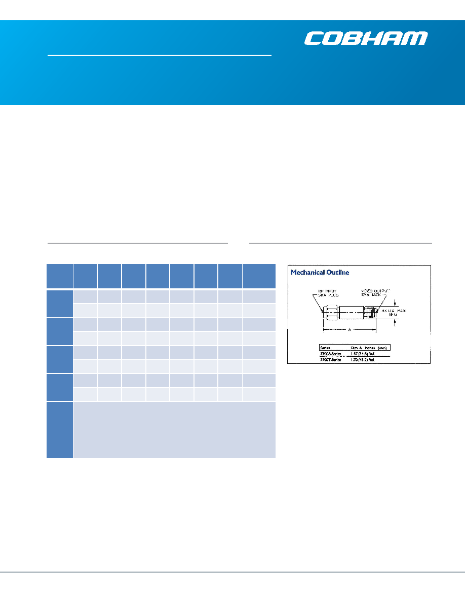
The 7700A series features a standard cylindrical coaxial pack-
age with SMA connectors and internal hermetically sealed
module containing microstrip hybridized circuit and chip de-
vices.
The 7700T provides capability for multiple, packaged tunnel
diodes with coaxial matching structure and coaxial capacitor.
DC return coil is included. Ease of diode selection and match
(unit-to-unit) is an advantage of this package.
These detectors provide a usable 67 dB dynamic range from
nominal TSS of -50 dBm, through maximum saturation at +17
dBm. Within this range, square law transfer response is
Specifications:
-50 dBm through -15 dBm, linear region is -15 dBm through
+5 dBm and saturation +5 dBm through +17 dBm. Above +17
dBm RF input power diode damage and subsequent burnout
occurs.
Tunnel diode detectors have excellent temperature stability,
very fast pulse response time, good RF match and broadband
frequency flatness. Open circuit voltage sensitivity (K) and
high power burnout are less than silicon based Schottky de-
tectors, but the tunnel detector’s relatively low video imped-
ance with no dc bias requirement enables dc and ac coupling
with video and log video post amplifiers.
Frequency
Range (GHz)
Voltage
Sensitivity
(K)
Min.
(2)
VSWR
Typ.
(3)
Flatness
Max. (dB)
Tss Typ.
(-dBm)
(4)
RF Bypass
Capacitance
Typ. (pF)
Rise Time
Typ. (nS)
(5)
Video
Resistance
Typ. (Ohms)
(6)
Part
Number
(1)
0.1 – 2.0
800
2.0:1
+0.5
50
100
13
120
7700A-0020
800
2.0:1
+0.5
50
100
13
120
7700T-0020
2.0 – 8.0
800
2.0:1
+0.6
50
20
4
120
7700A-0021
700
2.3:1
+0.6
50
20
4
120
7700T-0021
8.0 – 18.0
500
2.3:1
+1.0
50
12
3
100
7700A-0022
600
3.0:1
+1.0
50
12
3
100
7700T-0022
2.0 – 18.0
500
2.5:1
+1.5
50
20
4
100
7700A-0023
500
3.0:1
+1.5
50
20
4
100
7700T-0023
Notes:
1.
Detectors are normally supplied with negative (-) output voltage polarity, referenced to case ground. Positive
(+) output polarity is available for most parts. To designate, add suffix “P” to end of part numbers.
2.
Minimum open circuit voltage sensitivity (K) in mV/mW is measured at -20 dBm RF input power into 30K ohm,
external video load resistance (RL).
3.
VSWR measured at -20 dBm RF power input into 100 ohm, external video load resistance.
4.
Tangential signal sensitivity (Tss) is measured using a video amplifier restricted to 2 MHz bandwidth and
having a noise contribution of 3 dB maximum.
5.
Pulse rise time (tr) in nanoseconds, is measured into an external load (RL) of 100 ohms with 12 picofarads in
parallel.
6.
Video resistance is measured at -20dBm.
www.cobham.com
Data Sheet Subject to Change Without Notice
For further information please contact:
Cobham Sensor Systems
1001 Pawtuckett Blvd.
Lowell, MA 01854 USA
Tel: 877-COBHAM7 (877-262-4267)
Email: Sales.Space&Components@Cobham.com
相关PDF资料 |
PDF描述 |
|---|---|
| 770529-1 | .198, .200, .250" Centerline, 250 V, 13 A max. |
| 3-1376382-4 | 5mm Power Key Connectors |
| 3-1376383-4 | 5mm Power Key Connectors |
| 3-1376384-4 | 5mm Power Key Connectors |
| 3-1376385-4 | 5mm Power Key Connectors |
相关代理商/技术参数 |
参数描述 |
|---|---|
| 7700A-1000-B59 | 制造商:Belden Inc 功能描述:Coaxial Cable |
| 7700A-500-B59 | 制造商:Belden Inc 功能描述:Coaxial Cable 制造商:Belden Inc 功能描述:COAXIAL CABLE, 500FT, BLACK, Reel Length (Imperial):500ft, Reel Length (Metric):152.4m, Coaxial Cable Type:-, Conductor Size AWG:30AWG, Jacket Color:Black, Jacket Material:FEP (Fluorinated Ethylene Propylene), Impedance:75ohm , RoHS Compliant: Yes |
| 7700A-BLK-1000 | 制造商:Belden Inc 功能描述: |
| 7700B | 制造商:TT Electronics / BI Technologies 功能描述: |
| 7700H0021 | 制造商:未知厂家 制造商全称:未知厂家 功能描述:Interface IC |
发布紧急采购,3分钟左右您将得到回复。