- 您现在的位置:买卖IC网 > PDF目录357530 > 8P006SRV3205I15 (WHITE ELECTRONIC DESIGNS CORP) 3M X 16 MULTI DEVICE SRAM CARD, 150 ns, XMA68 PDF资料下载
参数资料
| 型号: | 8P006SRV3205I15 |
| 厂商: | WHITE ELECTRONIC DESIGNS CORP |
| 元件分类: | SRAM |
| 英文描述: | 3M X 16 MULTI DEVICE SRAM CARD, 150 ns, XMA68 |
| 封装: | CARD2-68 |
| 文件页数: | 5/10页 |
| 文件大小: | 120K |
| 代理商: | 8P006SRV3205I15 |
January 2002 Rev. 0 - ECO #xxxx
5
PCMCIA SRAM Memory Card
SRV30 Series
PC Card Products
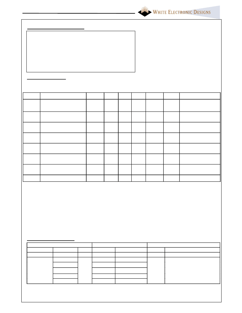
Absolute Maximum Ratings
Operating Temperature TA (ambient)
Commercial
Industrial
Storage Temperature
Commercial
Industrial
Voltage on any pin relative to VSS
VCC supply Voltage relative to VSS
0°C to +60 °C
-40°C to +85 °C
0°C to +60 °C
-40°C to +85 °C
-0.5V to +5.5V (1)
-0.5V to +7.0V
Notes:
Stress greater than those listed under “Absolute
Maximum Ratings” may cause permanent damage
to the device. This is a stress rating only and
functional operation at these or any other
conditions greater than those indicated in the
operational sections of this specification is not
implied. Exposure to absolute maximum rating
conditions for extended periods may affect
reliability.
Sym
ICC
Parameter
VCC Active Current
Density
All
Notes
1
Min
Typ
(3)
Max
25
Units
mA
Test Conditions
VCC = 5.25V
tcycle = 150ns
ICCS
VCC Standby Current
All
2, 4
!
< 1
10
mA
VCC = 5.25V
Control Signals = VCC
VCC = VCCMAX
Vin =VCC or VSS
VCC = VCCMAX
Vout =VCC or VSS
VCC= 3V
VCC= 5.25V
VCC= 3V
VCC= 5.25V
IOL = 3.2mA
ILI
Input Leakage Current
All
5, 6
±20
μA
ILO
Output Leakage Current
All
6
±20
μA
VIL
Input Low Voltage
All
6
0.9
1.6
V
VIH
Input High Voltage
Output Low Voltage
Output High Voltage
All
6
2.1
3.8
Vcc+0.5
Vcc+0.5
0.4
V
VOL
All
6
V
VOH
All
6
2.4
2.8
V
IOH = -2.0mA
Notes:
1. All currents are for x16 mode and are RMS values unless otherwise specified.
2. Control Signals: CE
#, CE
#, OE#, WE#, REG#.
3. Typical: VCC = 5V, T = +25C.
4. ICCS includes battery recharge current. Value depends on battery discharge level. ICCS min is specified for fully
charged battery. ICCS typical value is specified for battery discharge to 2.7V. ICCS max is specified for a fully
discharged battery (0V). Battery will recharge to 1.5V in 20 sec.
5. Values are the same for byte and word wide modes for all card densities.
6. Exceptions: Leakage currents on CE1#, CE2#, OE#, REG# and WE# will be < 500 μA when VIN = GND due to
internal pull-up resistors.
Battery Characteristics
CMOS Test Conditions: VIL = VSS ± 0.2V, VIH = 5V ± 0.2V
VCC = 3.3V or 5V
DC Characteristics
SRV31-34
Conditions
Parameter
Battery Life
Card
capacity
Density
All
2MB
4MB
8MB
12MB
16MB
Notes
(1)
(2)
Type I
min 10
18
18
12
10
9
Type II
min 10
40
40
30
25
20
Units
years
Normal operation, T=25C
months
(typical)
Battery backup time is a
calculated value and is not
guaranteed. This should not be
used to schedule battery
recharging. (Temp 25C)
Notes:
1. Battery Life refers to functional lifetime of battery.
2. Battery backup time is density and temperature dependent.
相关PDF资料 |
PDF描述 |
|---|---|
| 8P002SRV3103C15 | 1M X 16 MULTI DEVICE SRAM CARD, 150 ns, XMA68 |
| 8P006SRV3100I15 | 3M X 16 MULTI DEVICE SRAM CARD, 150 ns, XMA68 |
| 8P006SRV3301C15 | 3M X 16 MULTI DEVICE SRAM CARD, 150 ns, XMA68 |
| 8P006SRV3404I15 | 3M X 16 MULTI DEVICE SRAM CARD, 150 ns, XMA68 |
| 8P008SRV3104I15 | 4M X 16 MULTI DEVICE SRAM CARD, 150 ns, XMA68 |
相关代理商/技术参数 |
参数描述 |
|---|---|
| 8P-03AFFM-QL5A01 | 功能描述:M8 CONN 制造商:amphenol ltw 系列:* 零件状态:在售 标准包装:10 |
| 8P-03AFFM-QL5A02 | 功能描述:M8 CONN 制造商:amphenol ltw 系列:* 零件状态:在售 标准包装:10 |
| 8P-03AFFM-QL5A05 | 功能描述:M8 CONN 制造商:amphenol ltw 系列:* 零件状态:在售 标准包装:10 |
| 8P-03AFFM-QL5A10 | 功能描述:M8 CONN 制造商:amphenol ltw 系列:* 零件状态:在售 标准包装:10 |
| 8P-03AFFM-QL5B01 | 功能描述:M8 CONN 制造商:amphenol ltw 系列:* 零件状态:在售 标准包装:10 |
发布紧急采购,3分钟左右您将得到回复。