- 您现在的位置:买卖IC网 > PDF目录42453 > 93LC56AX/SN 256 X 8 MICROWIRE BUS SERIAL EEPROM, PDSO8 PDF资料下载
参数资料
| 型号: | 93LC56AX/SN |
| 元件分类: | PROM |
| 英文描述: | 256 X 8 MICROWIRE BUS SERIAL EEPROM, PDSO8 |
| 封装: | 0.150 INCH, PLASTIC, SOIC-8 |
| 文件页数: | 5/12页 |
| 文件大小: | 222K |
| 代理商: | 93LC56AX/SN |
93LC56A/B
DS21208C-page 2
1998 Microchip Technology Inc.
1.0
ELECTRICAL
CHARACTERISTICS
1.1
Maximum Ratings*
VCC...................................................................................7.0V
All inputs and outputs w.r.t. Vss ............... -0.6V to Vcc +1.0V
Storage temperature .....................................-65°C to +150°C
Ambient temp. with power applied ................-65°C to +125°C
Soldering temperature of leads (10 seconds) ............. +300°C
ESD protection on all pins................................................4 kV
*Notice: Stresses above those listed under “Maximum ratings” may
cause permanent damage to the device. This is a stress rating only and
functional operation of the device at those or any other conditions
above those indicated in the operational listings of this specification is
not implied. Exposure to maximum rating conditions for extended peri-
ods may affect device reliability.
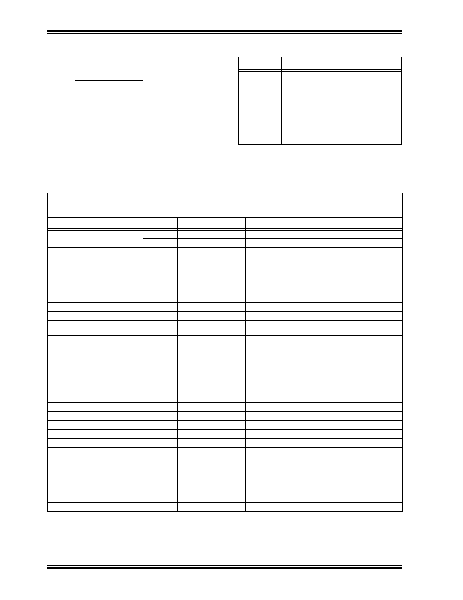
TABLE 1-1
PIN FUNCTION TABLE
Name
Function
CS
Chip Select
CLK
Serial Data Clock
DI
Serial Data Input
DO
Serial Data Output
VSS
Ground
NC
No Connect
VCC
Power Supply
TABLE 1-2
DC AND AC ELECTRICAL CHARACTERISTICS
All parameters apply over the specified
operating ranges unless otherwise
noted
Commercial (C):
VCC = +2.5V to +6.0V
Tamb = 0°C to +70°C
Industrial (I):
VCC = +2.5V to +6.0V
Tamb = -40°C to +85°C
Parameter
Symbol
Min.
Max.
Units
Conditions
High level input voltage
VIH1
2.0
Vcc +1
V
2.7V
VIH2
0.7 Vcc
Vcc +1
V
VCC < 2.7V
Low level input voltage
VIL1-0.3
0.8
V
VIL2
-0.3
0.2 Vcc
V
VCC < 2.7V
Low level output voltage
VOL1
—
0.4
V
IOL = 2.1 mA; Vcc = 4.5V
VOL2
—
0.2
V
IOL =100 A; Vcc = Vcc Min.
High level output voltage
VOH12.4
—
VIOH = -400 A; Vcc = 4.5V
VOH2Vcc-0.2
—
VIOH = -100 A; Vcc = Vcc Min.
Input leakage current
ILI
-10
10
A
VIN = VSS
Output leakage current
ILO
-10
10
A
VOUT = VSS
Pin capacitance
(all inputs/outputs)
CIN, COUT
—
7pF
VIN/VOUT = 0 V (Notes 1 & 2)
Tamb = +25°C, Fclk = 1 MHz
Operating current
ICC read
—
1
500
mA
A
FCLK = 2 MHz; VCC = 6.0V
FCLK = 1 MHz; VCC = 3.0V
ICC write
—
1.5
mA
Standby current
ICCS
—
1A
CS = VSS; DI = VSS
Clock frequency
FCLK
—
2
1
MHz
VCC > 4.5V
VCC < 4.5V
Clock high time
TCKH
250
—
ns
Clock low time
TCKL
250
—
ns
Chip select setup time
TCSS
50
—
ns
Relative to CLK
Chip select hold time
TCSH
0
—
ns
Relative to CLK
Chip select low time
TCSL
250
—
ns
Data input setup time
TDIS
100
—
ns
Relative to CLK
Data input hold time
TDIH
100
—
ns
Relative to CLK
Data output delay time
TPD
—
400
ns
Cl = 100 pF
Data output disable time
TCZ
—
100
ns
Cl = 100 pF (Note 2)
Status valid time
TSV
—
500
ns
Cl = 100 pF
Program cycle time
TWC
—
6ms
ERASE/WRITE mode
TEC
—
6
ms
ERAL mode
TWL
—
15
ms
WRAL mode
Endurance
—
1M
—
cycles
Note 1: This parameter is tested at Tamb = 25°C and FCLK = 1 MHz.
2: This parameter is periodically sampled and not 100% tested.
3: This application is not tested but guaranteed by characterization. For endurance estimates in a specific application, please consult the Total
Endurance Model which may be obtained on our website.
相关PDF资料 |
PDF描述 |
|---|---|
| 93LC56BT/ST | 128 X 16 MICROWIRE BUS SERIAL EEPROM, PDSO8 |
| 93LC56BX/SN | 128 X 16 MICROWIRE BUS SERIAL EEPROM, PDSO8 |
| 93LC56BXT/SNA23 | 128 X 16 MICROWIRE BUS SERIAL EEPROM, PDSO8 |
| 93LC56BT/SNC22 | 128 X 16 MICROWIRE BUS SERIAL EEPROM, PDSO8 |
| 93LC56AT/SN100 | 256 X 8 MICROWIRE BUS SERIAL EEPROM, PDSO8 |
相关代理商/技术参数 |
参数描述 |
|---|---|
| 93LC56AXT/SN | 功能描述:电可擦除可编程只读存储器 256x8 Rot Pin RoHS:否 制造商:Atmel 存储容量:2 Kbit 组织:256 B x 8 数据保留:100 yr 最大时钟频率:1000 KHz 最大工作电流:6 uA 工作电源电压:1.7 V to 5.5 V 最大工作温度:+ 85 C 安装风格:SMD/SMT 封装 / 箱体:SOIC-8 |
| 93LC56AXT-E/MC | 制造商:MICROCHIP 制造商全称:Microchip Technology 功能描述:2K Microwire Compatible Serial EEPROM |
| 93LC56AXTE/MS | 制造商:MICROCHIP 制造商全称:Microchip Technology 功能描述:2K Microwire Compatible Serial EEPROM |
| 93LC56AXT-E/MS | 制造商:MICROCHIP 制造商全称:Microchip Technology 功能描述:2K Microwire Compatible Serial EEPROM |
| 93LC56AXTE/MSG | 制造商:MICROCHIP 制造商全称:Microchip Technology 功能描述:2K Microwire Compatible Serial EEPROM |
发布紧急采购,3分钟左右您将得到回复。