- 您现在的位置:买卖IC网 > PDF目录42346 > 93MT80KBS90PBF 800 V, SCR PDF资料下载
参数资料
| 型号: | 93MT80KBS90PBF |
| 元件分类: | 晶闸管 |
| 英文描述: | 800 V, SCR |
| 文件页数: | 3/9页 |
| 文件大小: | 111K |
| 代理商: | 93MT80KBS90PBF |
www.irf.com
53-93-113MT..KB Series
3
Bulletin I27503 08/97
53MT.KB 93MT.KB 113MT.KB
Parameter
52MT.KB 92MT.KB 112MT.KB Units Conditions
51MT.KB 91MT.KB 111MT.KB
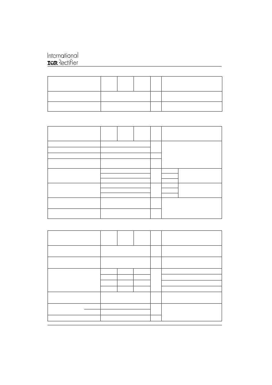
V
INS
RMS isolation voltage
4000
V
T
J
= 25oC all terminal shorted
f = 50Hz, t = 1s
dv/dt
Max. critical rate of rise
500
V/s
T
J
= T
J
max., linear to 0.67 V
DRM,
of off-state voltage (*)
gate open circuit
Blocking
(*) Available with dv/dt = 1000V/ms, to complete code add S90 i.e. 113MT160KBS90.
Triggering
53MT.KB 93MT.KB 113MT.KB
Parameter
52MT.KB 92MT.KB 112MT.KB Units Conditions
51MT.KB 91MT.KB 111MT.KB
P
GM
Max. peak gate power
10
W
T
J = TJ max.
P
G(AV)
Max. average gate power
2.5
I
GM
Max. peak gate current
2.5
A
-V
GT
Max. peak negative
10
V
gate voltage
V
GT
Max. required DC gate
4.0
V
TJ = - 40°C
voltage to trigger
2.5
TJ = 25°C
Anode supply = 6V, resistive load
1.7
TJ = 125°C
I
GT
Max. required DC gate
270
TJ = - 40°C
current to trigger
150
mA
TJ = 25°C
Anode supply = 6V, resistive load
80
TJ = 125°C
V
GD
Max. gate voltage
0.25
V
@ T
J = TJ max., ratedVDRMapplied
that will not trigger
I
GD
Max. gate current
6
mA
that will not trigger
Thermal and Mechanical Specifications
53MT.KB 93MT.KB 113MT.KB
Parameter
52MT.KB 92MT.KB 112MT.KB Units Conditions
51MT.KB 91MT.KB 111MT.KB
T
J
Max. junction operating
-40 to 125
°C
temperature range
T
stg
Max. storage temperature
-40 to 125
°C
range
R
thJC
Max. thermal resistance,
0.18
0.14
0.12
K/W
DC operation per module
junction to case
1.07
0.86
0.70
DC operation per junction
0.19
0.15
0.12
120° Rect condunction angle per module
1.17
0.91
0.74
120° Rect condunction angle per junction
R
thCS
Max. thermal resistance,
0.03
K/W
Per module
case to heatsink
Mounting surface smooth, flat an greased
T
Mounting
to heatsink
4 to 6
Nm
torque ± 10%
to terminal
3 to 4
wt
Approximate weight
225
g
A mounting compound is recommended and the
torque should be rechecked after a period of 3
hours to allow for the spread of the compound.
Lubricated threads.
相关PDF资料 |
PDF描述 |
|---|---|
| 91MT160KBS90PBF | 1600 V, SCR |
| 91MT140KBS90PBF | 1400 V, SCR |
| 91MT120KBS90PBF | 1200 V, SCR |
| 91MT100KBS90PBF | 1000 V, SCR |
| 92MT80KBS90PBF | 800 V, SCR |
相关代理商/技术参数 |
参数描述 |
|---|---|
| 93MT80KPBF | 制造商:VISHAY 制造商全称:Vishay Siliconix 功能描述:Three Phase Controlled Bridge (Power Modules), 55 A to 110 A |
| 93MT80KS90PBF | 制造商:VISHAY 制造商全称:Vishay Siliconix 功能描述:Three Phase Controlled Bridge (Power Modules), 55 A to 110 A |
| 93NJ10RE | 制造商:OHMITE 制造商全称:Ohmite Mfg. Co. 功能描述:Lead Free Vitreous Enamel Molded Axial Term. Wirewound, 5% Tolerance Standard |
| 93NJ1K0E | 制造商:未知厂家 制造商全称:未知厂家 功能描述:Lead Free Vitreous Enamel Molded Axial Term. Wirewound, 5% Tolerance Standard |
| 93NJ1R0 | 制造商:Ohmite Mfg Co 功能描述: |
发布紧急采购,3分钟左右您将得到回复。