- 您现在的位置:买卖IC网 > PDF目录360624 > 945 Converter PDF资料下载
参数资料
| 型号: | 945 |
| 英文描述: | Converter |
| 中文描述: | 转换器 |
| 文件页数: | 3/6页 |
| 文件大小: | 223K |
| 代理商: | 945 |
A
3
C
1
Models 940 and 945 DC Transmitters
http://www.calex.com
2401 Stanwell Drive
Concord, CA 94520-4841
(510) 687-4411 Fax (510) 687-3333
Mounting Kit
The MK940 mounting kit is an optional printed circuit board
that provides the necessary potentiometers and a connector
for a complete turnkey system.
The 940/MK940, when ordered as a combination, is shipped
from the factory configured as a 0 to +10 Volt input, 4 to 20mA
output, isolated transmitter. The 945/MK940, when ordered
as a combination, is shipped from the factory configured as
a 0 to 50 mV input, 4 to 20 mA output, isolated transmitter.
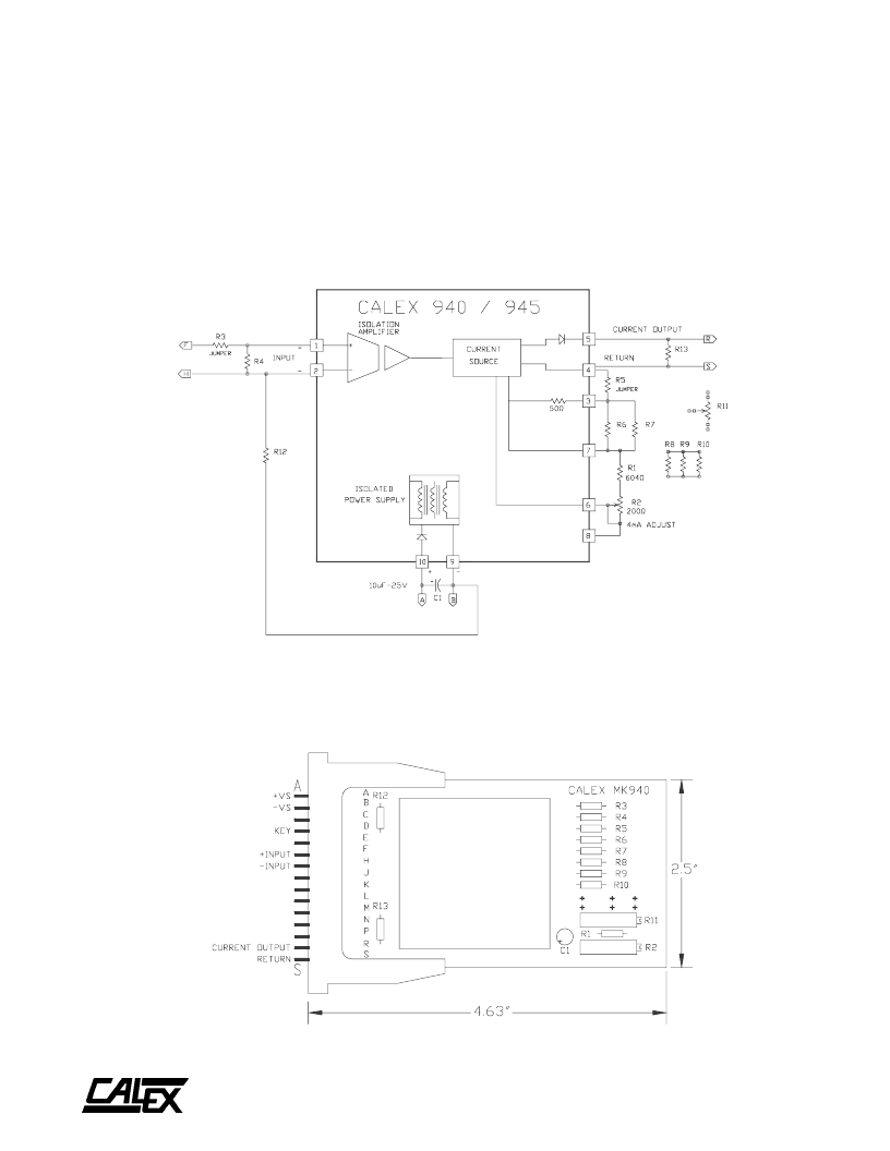
Note in the schematic, Figure 1, that C1, R1, R2, R3, and R5
are included on the board. The other designated components
are user supplied for other applications. Also note that R8
through R11 are not connected to the rest of the circuit. For
24 VDC operation, add a “-24” to the MK940, i.e. 945/MK940-
24
Figure 2 shows the outline of the MK940 card and the lettered
pin assignments. The card includes a Model 015 connector
with edge guides and has eyelets for soldering wires. The
components described as jumpers are wire connections
although they have a ceramic body the size of a W resistor.
FIGURE 2.
MK940 Card
FIGURE 1.
MK940 Schematic
NOTE:
C1, R1, R2, R3, R5 ARE INCLUDED.
ALL OTHER COMPONENTS ARE USER
SUPPLIED FOR SPECIFIC APPLICATIONS.
Model 940/945
Powered by ICminer.com Electronic-Library Service CopyRight 2003
相关PDF资料 |
PDF描述 |
|---|---|
| 945L4Y-2D-001 | ULTRASCHALLSCHALTER ROSTFREIER STAHL PNP |
| 945L4Y-2D-002 | ULTRASCHALLSCHALTER ROSTFREIER STAHL NPN |
| 9464 | SOCKET DIN/SURFACE FOR 8534 TIMER |
| 9412 | INDUSTRIERELAIS SOCKEL CLIP 2POL RELAIS |
| 9413 | INDUSTRIERELAIS SOCKEL CLIP 2POL RELAIS |
相关代理商/技术参数 |
参数描述 |
|---|---|
| 945 DIE | 制造商:Texas Instruments 功能描述: |
| 945 WAF | 制造商:Texas Instruments 功能描述: |
| 945 285 991 | 制造商:Gelia 功能描述:Bulk |
| 945 295 991 | 制造商:Gelia 功能描述:Bulk |
| 945 407 991 | 制造商:Gelia 功能描述:Bulk |
发布紧急采购,3分钟左右您将得到回复。