- 您现在的位置:买卖IC网 > Datasheet目录59 > A1354KKT-T (Allegro Microsystems Inc)IC SENSOR HALL EFFECT 4-SIP Datasheet资料下载
参数资料
| 型号: | A1354KKT-T |
| 厂商: | Allegro Microsystems Inc |
| 文件页数: | 14/23页 |
| 文件大小: | 540K |
| 描述: | IC SENSOR HALL EFFECT 4-SIP |
| 产品培训模块: | Current Sensor |
| 标准包装: | 500 |
| 传感范围: | 0.1% ~ 0.2%/G |
| 类型: | 线性场传感器 |
| 电源电压: | 4.5 V ~ 16 V |
| 电流 - 电源: | 9mA |
| 输出类型: | 数字式, PWM 编码 |
| 特点: | 高精度 |
| 工作温度: | -40°C ~ 125°C |
| 封装/外壳: | 4-SIP |
| 供应商设备封装: | 4-SIP |
| 包装: | 散装 |
| 产品目录页面: | 1139 (CN2011-ZH PDF) |
| 其它名称: | 620-1317 |
Overview
Programming is accomplished by sending a series of input voltage
pulses serially through the VCC pin of the device. Unique combi-
nations of different voltage amplitude pulses control the internal
programming logic of the device to select a programmable param-
eter and set its value. There are three voltage levels that must be
taken into account when programming using a high voltage pulse,
VPH
(consisting of a V
P(LOW)
V
P(HIGH)
V
P(LOW)
sequence),
and a mid voltage pulse, VPM
(consisting of a V
P(LOW)
V
P(MID)
V
P(LOW)
sequence). The low voltage level, V
P(LOW)
, separates the
VPH and VPM programming pulses.
The 1354 features Try mode, Blow mode, and Lock mode:
" In Try mode, the value of multiple programmable parameters
may be set and measured simultaneously. The parameter values
are stored temporarily, and reset after cycling the supply volt-
age.
" In Blow mode, the value of a single programmable parameter
may be set, measured, and permanently set by blowing solid-
state fuses internal to the device. Additional parameters may be
blown sequentially. This mode is used for blowing the device-
level fuse, which permanently blocks the further programming
of all parameters.
" Lock mode prevents all future programming of the device. This
is accomplished by blowing a special fuse using blow mode.
The programming sequence is designed to help prevent the device
from being programmed accidentally; for example, as a result of
noise on the supply line. Although any programmable variable
power supply can be used to generate the pulse waveforms, Allegro
highly recommends using the Allegro Sensor IC Evaluation Kit,
available on the Allegro website On-line Store. The manual for that
kit is available for download free of charge, and provides addi-
tional information on programming these devices.
Definition of Terms
Register The section of the programming logic that controls the
choice of programmable modes and parameters.
Bitfield The internal fuses unique to each register, represented as
a binary number. Incrementing the bitfields of a particular register
causes its programmable parameter to change, based on the internal
programming logic.
Key A series of mid voltage pulses used to select a register, with a
value expressed as the decimal equivalent of the binary value. The
LSB of a register is denoted as key 1, or bitfield 0.
Code The number used to identify the combination of fuses
activated in a bitfield, expressed as the decimal equivalent of the
binary value. The LSB of a bitfield is denoted as code 1, or bit 0.
Addressing Incrementing the bit field code of a selected regis-
ter by serially applying a pulse train through the VCC pin of the
device. Each parameter can be measured during the addressing pro-
cess, but the internal fuses must be blown before the programming
code (and parameter value) becomes permanent.
Fuse Blowing Applying a high pulse of sufficient duration to
permanently set an addressed bit by blowing a fuse internal to the
device. Once a bit (fuse) has been blown, it cannot be reset.
Blow Pulse A high pulse of sufficient duration to blow the
addressed fuse.
Cycling the Supply Powering-down, and then powering-up the
supply voltage. Cycling the supply is used to clear the program-
ming settings in Try mode.
Programming Guidelines
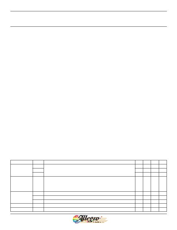
Programming Pulse Requirements, Protocol at T
A
= 25 癈
Characteristic Symbol
Notes
Min. Typ. Max. Unit
Programming
Voltage
V
P(LOW)
Measured at the VCC pin.
4.5 5 5.5 V
V
P(MID)
13 15 16 V
V
P(HIGH)
26 27 28 V
Programming
Current
I
P
Minimum supply current required to ensure proper fuse blowing. In addition, a
minimum capacitance, C
BLOW
= 0.1 糉, must be connected between the VCC and
GND pins during programming to provide the current necessary for fuse blowing.
The blowing capacitor should be removed and the load capacitance used for properly
programming duty cycle measurements.
300 mA
Pulse Width
t
LOW
Duration of V
P(LOW)
for separating V
P(MID)
and V
P(HIGH)
pulses.
40 約
t
ACTIVE
Duration of V
P(MID)
and V
P(HIGH)
pulses for register selection or bitfield addressing. 40 約
t
BLOW
Duration of V
P(HIGH)
pulses for fuse blowing.
40 約
Pulse Rise Time t
Pr
Rise time required for transitions from V
P(LOW)
to either V
P(MID)
or V
P(HIGH)
.
5 100 約
Pulse Fall Time
t
Pf
Fall time required for transitions from V
P(HIGH)
to either V
P(MID)
or V
P(LOW)
.
5 100 約
High Precision 2-Wire Linear Hall Effect Sensor IC
with Pulse Width Modulated Output
A1354
13
Allegro MicroSystems, Inc.
115 Northeast Cutoff
Worcester, Massachusetts 01615-0036 U.S.A.
1.508.853.5000; www.allegromicro.com
相关PDF资料 |
PDF描述 |
|---|---|
| A1356LKB-T | IC SENSOR HALL EFFECT 3 SIP |
| A1361LKTTN-T | IC HALL EFFECT SENSOR LN 4-SIP |
| A1374EKB-T | IC SENSOR HALL EFFECT PREC 3-SIP |
| A1422LK | IC SENSOR HALL EFFECT AC 4-SIP |
| A1425LK | IC SENSOR HALL EFFECT AC 4-SIP |
相关代理商/技术参数 |
参数描述 |
|---|---|
| A1354KKTTN-T | 功能描述:IC HALL EFFECT SENSOR 2WIRE 4SIP RoHS:是 类别:传感器,转换器 >> 磁性 - 霍尔效应,数字式开关,线性,罗盘 (IC) 系列:- 标准包装:1 系列:- 传感范围:20mT ~ 80mT 类型:旋转 电源电压:4.5 V ~ 5.5 V 电流 - 电源:15mA 电流 - 输出(最大):- 输出类型:数字式,PWM,8.5 位串行 特点:可编程 工作温度:-40°C ~ 150°C 封装/外壳:20-SSOP(0.209",5.30mm 宽) 供应商设备封装:20-SSOP 包装:Digi-Reel® 其它名称:AS5132-HSST-500DKR |
| A1354P1-2 | 制造商:APEM 功能描述: |
| A1354P1-6 | 功能描述:SWITCH HARDWARE RoHS:是 类别:开关 >> 配件 系列:- 标准包装:100 系列:- 其它名称:886.0007886.0007-ND |
| A1354P2-4 | 制造商:APEM 功能描述: |
| A1354P2-5 | 功能描述:SWITCH HARDWARE RoHS:是 类别:开关 >> 配件 系列:- 标准包装:100 系列:- 其它名称:886.0007886.0007-ND |
发布紧急采购,3分钟左右您将得到回复。